As indicated on the literature page, there really are a gazillion webpages that teach you how to connect a led or a button to your Arduino compatible board.
However, we do provide a primer on how to connect your sensors and actuators to your Stickuino on this page. Don’t expect full tutorials, extensive walkthroughs or code examples. Arduino is all about experimenting and learning from what’s already been done.
Be sure to read up on the sensors and actuators themselves, before you start working on the example circuits.
ALWAYS DISCONNECT YOUR STICKUINO FROM POWER WHEN BUILDING/MODIFYING YOUR CIRCUITS!a
Note that there are many roads that lead to Rome and the breadboard examples are just showing one possible (not necessarily the only, not necessarily the best) way to hook things up. For a more detailed look, the images can be enlarged by clicking on them. The Stickuino pins used for sensors and actuators in the examples may usually be reconfigured in your code if you need certain specific pins for specific sensors or actuators.
Remember that you are allowed to use libraries (with some exceptions concerning timers, scheduling and debouncing, see the requirements page). Use this force wisely.
Using the breadboard
The bre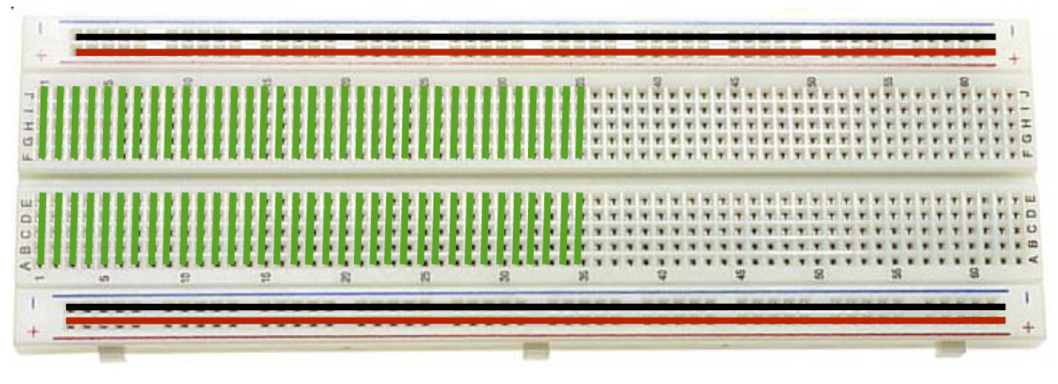 adboard in your kit is a very useful construction base for prototyping of electronics. It offers a solderless and therefore reusable way to build and experiment with electronic circuits. You’ll be building most of your circuits on this breadboard. There are a few things to know about your breadboard:
- The holes that are marked with a red line and a plus sign are all connected together. This row of holes is supposed to be used for the supply voltage by connecting the 5V pin of your Stickuino to one of the holes in this row. In this way, you’ll have 5V power available along the whole side of your breadboard.
- The same goes for the holes that are marked with a blue line and a minus sign. This row of holes is supposed to be used for ground by connecting one of the holes to one of the GND pins of your Stickuino.
- There are many breadboards (depending on manufacturer) where these two power rails are split into two non-connected parts: one for the left-hand side of the breadboard and one for the right-hand side. In that case, the red and blue lines show a gap. You can easily connect these parts together by bridging the gap using jumper wires if you need.
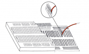
- The other holes are connected together column-wise and are used to connect the actual components to each other or to your Stickuino. The columns are numbered 1 through 63. The holes A through E with the same column number are connected together. The holes F through J in the same column are also connected together. However, A – E is not connected to F – J.
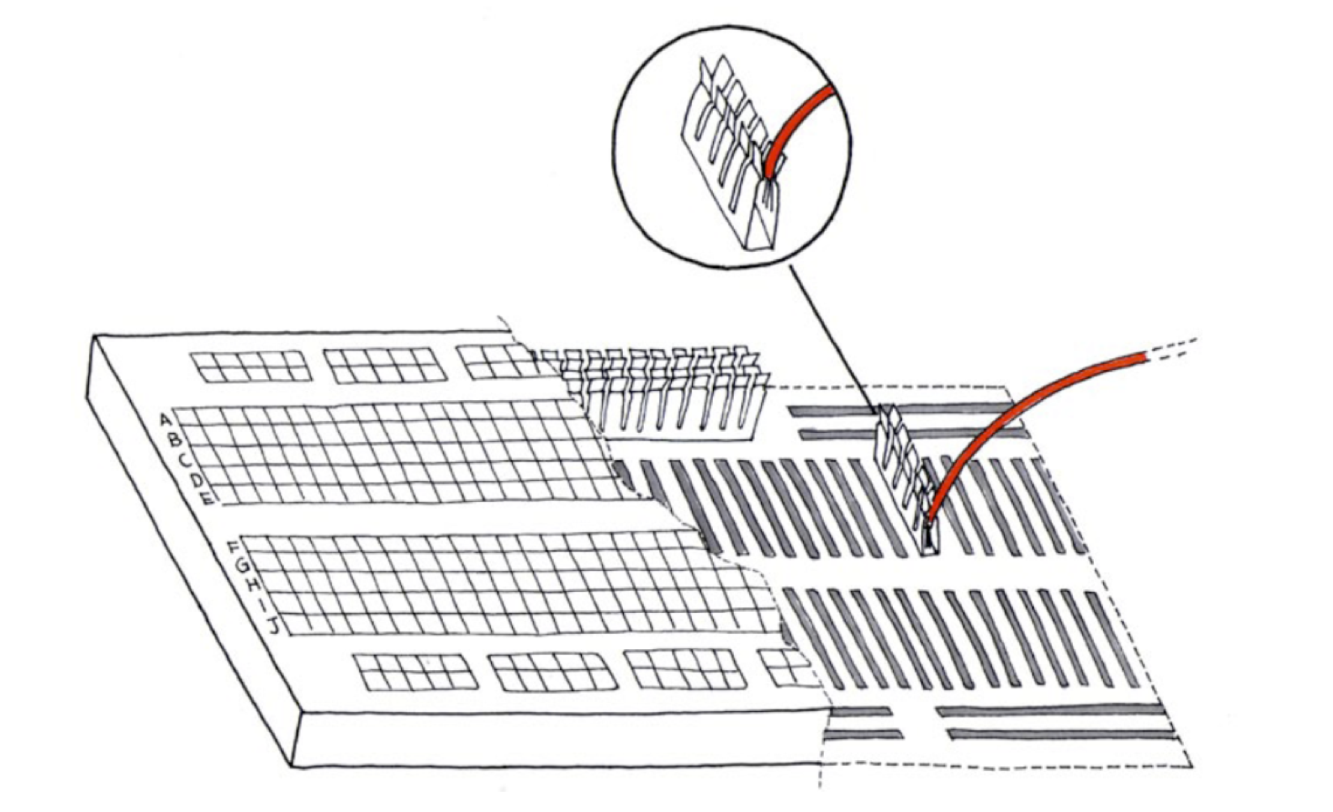
A picture says more than a thousands words. Check it out and you’ll understand.
The jumper wires in your kit go together with your breadboard. They are used to interconnect components that are not already interconnected through the breadboard. Note that you can sometimes save on the number of jumper wires required for your circuit by making use of the leads on the components themselves to bridge the distance between two points.
A note on resistor values
 The breadboard examples shown below may use different resistor values (with a different color code) than the ones you have available. You only have three values, for very distinct purposes.
- ‘Everything led’ will be using the 220 Ohm resistors. This includes the led based backlight of the LCD display.
- The DS18B20 compatible temperature sensor will be using a 2.2k Ohm resistor on the 1-wire bus.
- Every other sensor or actuator that needs resistors will be using the 10k Ohm resistors. These include the push buttons, magnetic contact sensor, light sensor and mosfet.
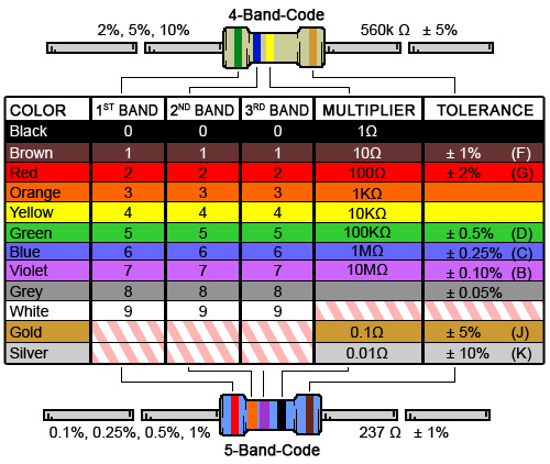
If you are wondering how to recognize these values – or want to learn in general about the color coding bands on resistors – use one of the many resistor color code calculators or tables out there.
Connecting a led
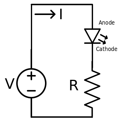 If you just want to light up a led, you may build the basic led circuit and connect the positive and negatives sides of the circuit to the 5V and GND pins of the Stickuino. However, if you want to control a led, you need to connect the positive side to one of the I/O pins of the Stickuino. It basically becomes a controllable power supply to the led.
As explained during the embedded systems and sensors lectures, a led needs a resistor in series to limit the current flow. If you forget about this, the led will burn, but only once.
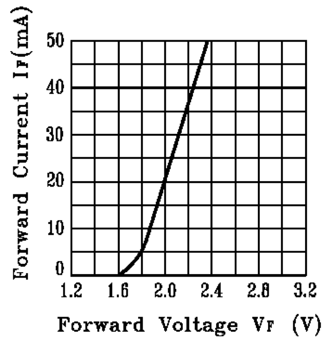
A nice current for a led would be 15 milliampere. This is well within the tolerable range of both the led and the Stickuino pin, which can supply a maximum of 40 milliampere.
Most leds have a forward voltage of (i.e. burn up) about 1.7 Volt at that current level, although this may vary a little by color. This means that 3.3 Volt of the 5 Volt that the Stickuino supplies needs to be burnt by something else: the series resistor.
 A 220 Ohm resistor will do nicely as most leds have a forward voltage of about 1.7 Volt when 15 milliampere flows through. That good old Voltage (V) = Current (I) * Resistance (R) formula will then lead to R = V/I = 3.3/0.015 = 220 Ohm.
The positive side of the led is indicated by the longer leg. Note that you may put the resistor on either side, as long as it is in series. And note that connecting the led the wrong way around – as in: negative side on the supply voltage and positive side on GND – will not harm the led. After all, it is a light emitting diode and a diode works as an electronic valve, letting current pass through in only one way and blocking it the other way.
As far as code is concerned, have a look at the Arduino Blink example that’s available in the IDE. But remember that sensors that excessive delays in your code are unwanted, as explained during the lectures.
If you want to dim a led, have a look at the Arduino Fading example. In the latter case, the led needs to be connected to one of the PWM pins of the Stickuino, indicated by a tilde (~) on the pcb.
Connecting an RGB led
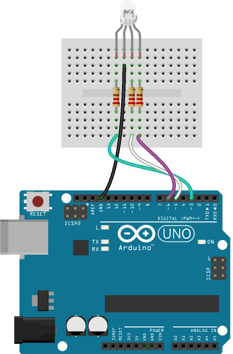
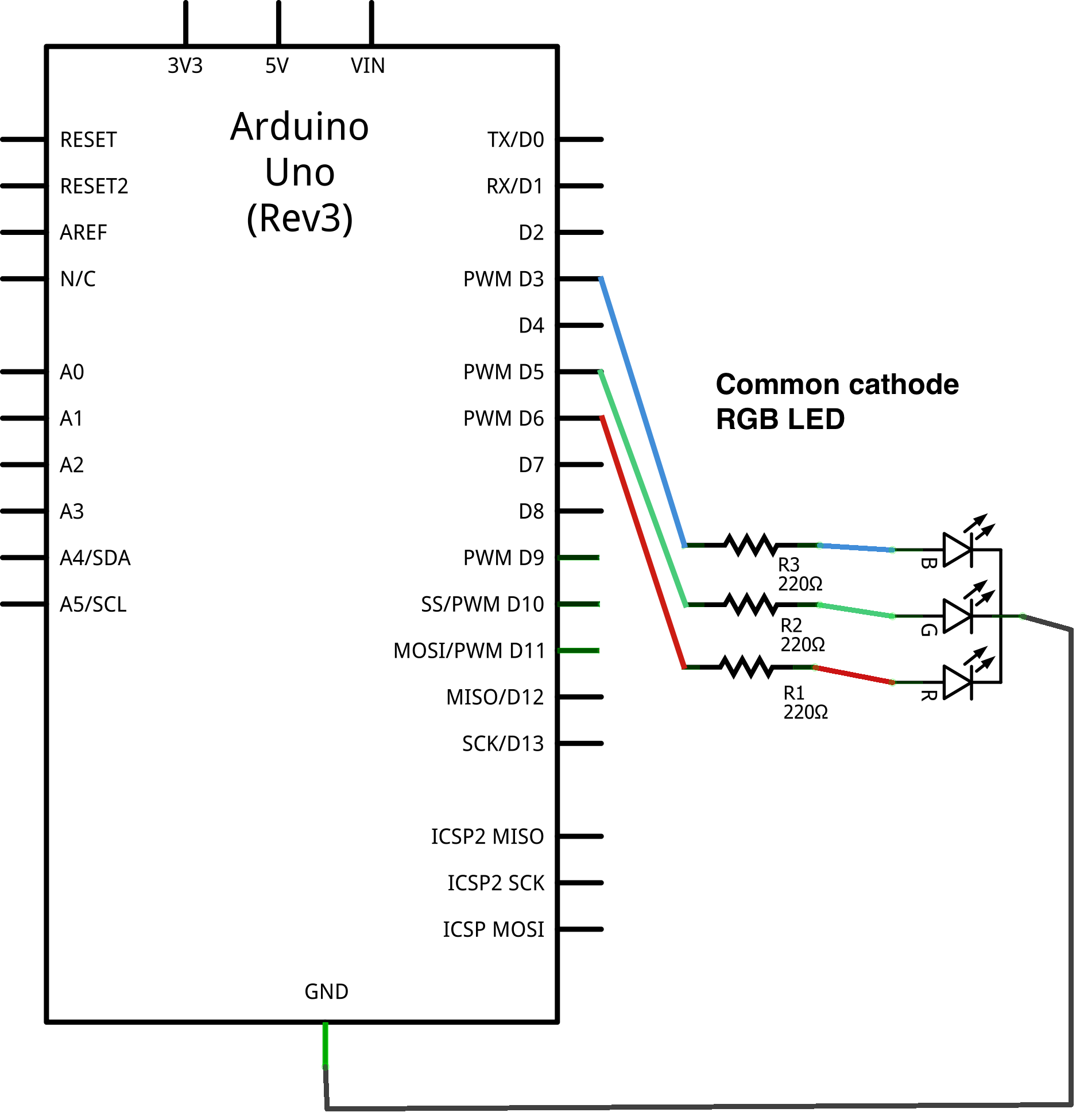 Remember that an RGB led contains three leds in one package.
Common cathode leds share a common negative leg (the longest one). Each individual led needs its own 220 Ohm resistor. One resistor in series with the negative leg will not do. (Try to think of the reason why.) Note that finding the longest leg might be a bit difficult as on certain leds it’s barely longer than the other pins, but you’ll manage.
To light up the RGB led you need to connect the positive sides to your microcontroller I/O pins (one for each color) and the common leg to the negative power supply pin (GND). Writing a HIGH (1) value to the corresponding pin will light up a color. Writing a LOW (0) value will turn it off.
If dimming of each individual led is required, each led should be connected to a PWM pin of your Stickuino.
Code-wise an RGB led is not that different from any other led. The Arduino Blink and Fading examples will quickly get you on track.
Connecting a push button
The naive way to connect a push button is to connect one side of the button to 5V and the other side to one of the Stickuino pins. The idea would be: if the button is pressed the pin senses 5V and if it’s not pressed the pin senses nothing. The error in this line of thinking is the assumption that nothing means 0V or GND, and that turns out not to be the case.
As explained during one of embedded systems and sensors lectures, unconnected Stickuino pins configured as INPUT are floating and may switch between sensing HIGH and LOW values all the time. As a push button is a Normally Open (NO) contact, connecting it the naive way essentially creates a floating pin whenever the button is not being pressed. So, a push button that is not being pressed may still seem to be pressed at times if you connect it the naive way.
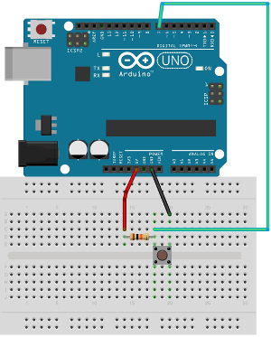
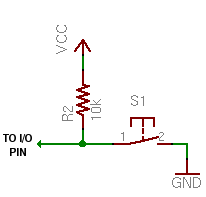 To prevent a floating pin, such a pin – and hence the push button – needs to be connected to a steady reference voltage, through a resistor. This resistor is known as a pull-up or pull-down resistor, as it pulls the floating pin up or down to a certain steady voltage level, 5V or GND respectively. Only then the button state can be reliably read. 10K Ohm resistors will do fine as either pull-up or pull-down resistors.
If a pull-up resistor is used, the other side of the button needs to be connected to GND. A pull-down resistor requires 5V on the other side of the button. For certain technical reasons pull-up resistors are usually preferred to pull-down resistors and that’s what we’ll use here.
Note that the use of pull-up resistors inverts the readings of the button states: whenever the button is pressed, the Stickuino pin senses a LOW value and while the button is not pressed, a HIGH value is being sensed.
Be sure to read up on the topic of pull-up and pull-down resistors, so that you fully understand how they work and understand the difference.
From a coding point of view, have a look at the Arduino Button example, but note that it uses a pull-down resistor instead of a pull-up resistor. As explained during the lectures, mechanical buttons usually require debouncing.
Connecting a magnetic contact sensor
Fortunately, a magnetic contact sensor is very similar to a push button from a hardware and software point of view. Both are binary switches, both need pull-up resistors. The main difference is that a magnetic contact sensor is a Normally Closed (NC) contact. See the push button example for hooking it up.
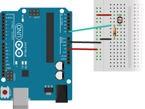
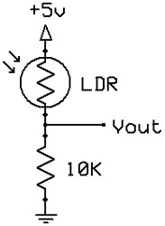
Connecting a light sensor
The light sensor is a Light Dependent Resistor (LDR). It’s just a resistor, but with a twist: its resistance varies according to the amount of light it is exposed to. There’s an inverse correlation: the lower the light level the higher the resistance and vice versa. The resistance ranges from several thousand to almost a million Ohm.
 An LDR is an analog sensor. It would be nice if the Stickuino could somehow directly read the resistance of the LDR on one of its analog pins. This, unfortunately, is not possible, as a microcontroller is not very well suited for sensing resistance.
It is, however, very good at sensing voltage, and to be able to read this analog sensor, we need to convert resistance to voltage. Fortunately, this is quite easy as resistance and voltage are linearly related and conversion is automatic.
But still, directly connecting the LDR to one of the analog pins will not do. A voltage divider is needed using a reference resistor of a known fixed value. A 10k Ohm resistor as fixed resistor will do fine for this type of LDR.
The voltage burnt up by the LDR can be measured and compared to the voltage burnt up by the fixed resistor. In this way we are able to calculate the resistance of the LDR. For instance: if the analog pin senses 1V we know that the LDR burns up 4V of the supplied 5V. The LDR resistance must then be 4 times as high as the fixed value, or 40k Ohm in this case.
Be sure to read on the topic of voltage dividers so that you fully understand how they work. Note that the voltage read at the analog pin is mapped to a 0 .. 1023 range (10 bit resolution A/D conversion), with 1023 standing for 5V and 0 standing for 0V / GND.
As far as code is concerned: have a look at some example code for reading an LDR. Also, the generic Arduino Analog Input example should work with an LDR.
Connecting a motion sensor
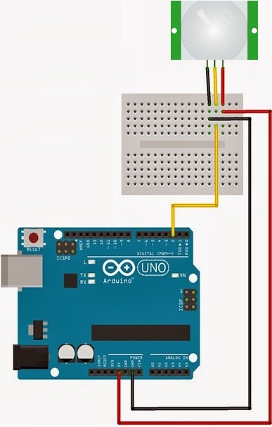 Although its internal workings are quite advanced, from the point of view of hooking it up to your Stickuino the motion sensor is just is a binary sensor: it outputs a HIGH or LOW value depending on whether it senses (or recently sensed) motion. In fact, for all practical purposes it may be considered to be switch, just like a push button or a magnetic contact sensor.
There are, however, some specific points of attention as well:
- A pull-up or pull-down resistor should not be used as the module already takes care of that.
- You might need to bend the pins to be able to use the module on your breadboard. Better yet: connect / solder some (jumper) wires to the connector and use it away from the breadboard. Soldering stations are available during practical assistance for this purpose. Or use insulating tape, a plastic connector (kroonsteentje in Dutch) or whatever other means you find appropriate for this purpose.
- The module features a number of hardware configuration options: a (solder or physical) jumper that sets whether the module keeps triggering while it senses motion or only triggers once, and two pots that by turning adjust the sensitivity of the sensor and the duration of the HIGH output after sensing motion. The pot that sets the duration of the HIGH output should be turned counter clockwise at first (= as little time HIGH as possible).
- When the sensor turns from HIGH (motion) to LOW (no motion) it will not sense any motion for several seconds. Also, it will take a minute or so to stabilize after applying power to the sensor. In general, you’ll find this one of the more finicky sensors in your kit. See the sensors and actuators page for detailed specifications.
From a coding point of view, have a look at the Arduino Button example, once more. As this is not a mechanical switch, contact bounce is not one of your problems here and hence debouncing won’t be required for this sensor.
Connecting a temperature sensor
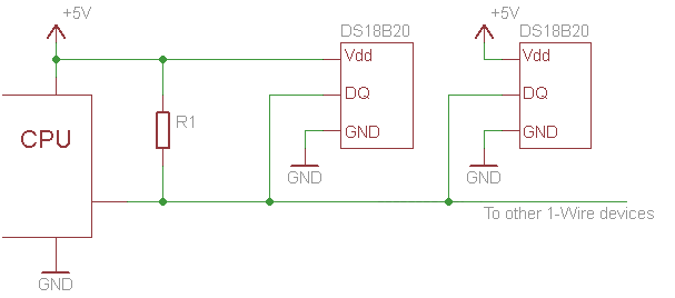 The temperature sensor in your kit, although humble in appearance, is quite advanced. It’s a digital sensor that uses the 1-wire protocol to communicate with a microcontroller. 1-wire is a serial communication protocol that supports multiple devices sharing a single data bus.
To differentiate between devices on the bus, each device has its own address. Although the temperature sensor will be the only device on the bus in our case, we still need to address it. Fortunately, finding the address of a device on the bus and using the address for further communication is all handled by a number of libraries. But more on that later. Let’s first connect the sensor.
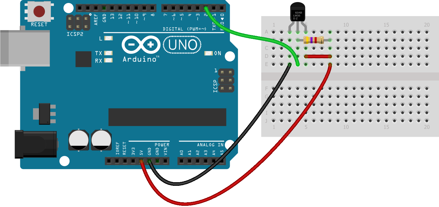 Don’t let the 1-wire name fool you: connecting the temperature sensor actually takes 3 wires. The name comes from the fact that in a certain mode a single wire can be used for power as well as for data, but we’ll be using dedicated separate wires for these. Connecting is straightforward: a single wire for 5V, GND and data. There is a catch, however: the 1-wire bus needs a pull-up resistor on the data bus. Use a 2.2k Ohm resistor for this. Some sources suggest a 4.7k Ohm resistor but it’s not critical and the ideal value varies with wire length anyway.
The temperature sensor is smart enough to figure out the temperature in degrees Celsius by itself and communicate this value to the microcontroller when asked to do so. But as it is using the 1-wire protocol for this, getting the value is a bit more involved code-wise than just reading a Stickuino pin. Fortunately, there are two libraries available to help you out.
The first one is a generic 1-wire library that takes care of the 1-wire protocol. It’s not included with the Arduino IDE; you have to install it yourself. The easiest way to do this is using the Library Manager that is included in the Arduino IDE, available from the menu under Tools > Manage Libraries. Just search for OneWire and install this library authored by Paul Stofregen (et al.).
Even if you have a 1-wire library that takes care of all the bus specifics, there are still a lot of device specific things that need to be taken care of: each type of device has its own commands and registers that you can read or write.
If you want, you can leave it at this and just use the raw 1-wire commands to interface with your temperature sensor using Paul Stofregen’s 1-wire library. An example for the DS18B20 compatible temperature sensor that’s part of your kit is included with the 1-wire library and available through the Examples menu of the Arduino IDE after installation of the library.
Adding a second DS18B20 specific library, that works on top of the first one, may be a little more convenient: it takes care of all the details specific to the type of temperature sensor that you’ll be using. It basically provides you a single statement command to read the temperature. This library can also be conveniently installed using the Arduino IDE Library Manager. Open the Library Manager, search for DallasTemperature and install this library authored by Miles Burton. If you haven’t done so, you’ll be prompted to install the OneWire library as well, which is a dependency.
Again, examples are included with this library as well and available through the Examples menu of the Arduino IDE after installation. Have a look at these!
Connecting a distance sensor
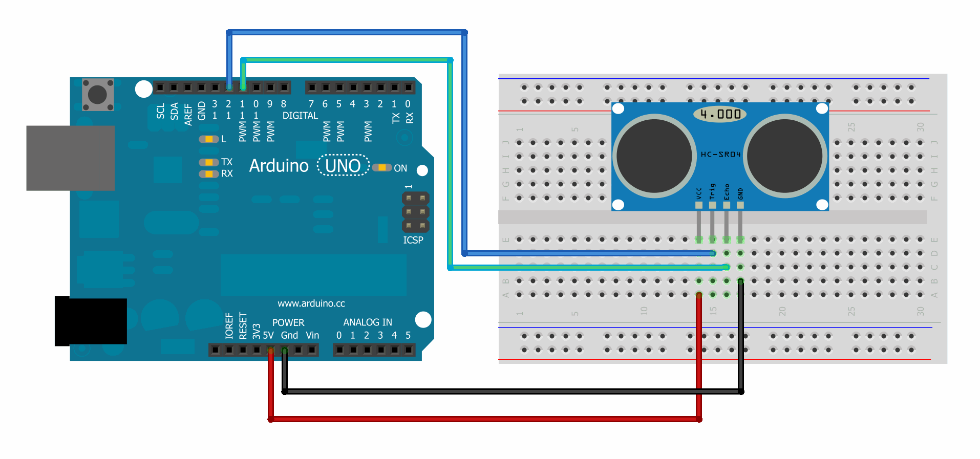 Connecting the ultrasonic distance sensor is straightforward: just four wires without any additional components. The protocol to get the sensor to work is a bit more involved though.
Besides the usual 5V and GND pins, there are two pins labeled trigger and echo. The basic operation of the sensor is as follows:
- The sensor is triggered by setting the trigger pin to HIGH for a sufficiently long time (just 10 microseconds will do).
- The sensor will now generate a series of 8 inaudible acoustic pulses, which may or may not be reflected by an object.
- If the sensor receives an echo, it will output a HIGH signal on the echo pin that lasts as long as it took the acoustic pulses to return to the sensor (i.e. the round-trip time or RTT).
By measuring the duration of the HIGH output on the echo pin, using the Stickuino, and taking the speed of sound into account, it’s possible to determine the distance between the sensor and an object in front of it. However, this requires precise time measurements and the process should not be interrupted by other concurrent events.
Fortunately, to help you out code-wise, there are a number of raw examples, as well as a library. The library, authored by Tim Eckel, is called NewPing and is again available from the Library Manager. Two words of warning:
- The pulseIn function that some of the examples are using is a blocking function call. That does not need to be a problem, as long as you take it into account; use a sensible (short) timeout value to handle the case that there’s no object in front of the sensor and hence no echo.
- The library may be used in a non-blocking way, but it does require the use of a timer interrupt (timer2 to be specific), which is a scarce resource. Although you are allowed to use this library, it does mean that you’ll lose PWM functionality on pins 3 and 11.
Connecting an LCD display
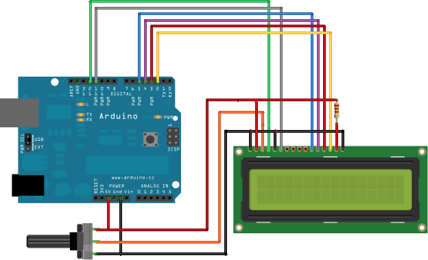 Connecting the LCD display is one of the more challenging tasks, hardware-wise. See the picture for an overview of which LCD pin should be connected to which Stickuino pin.
Note that pin 15 and 16, which are located on the right hand side of the LCD display, are pins that connect to the backlight of the LCD display. As the backlight is led-based, you shouldn’t be surprised to see the obligatory current limiting resistor connected in series with the positive side. This resistor should, once again, be a 220 Ohm resistor. However tempting, do not try to control the LCD backlight from one of the Stickuino pins, as it draws too much power from the pin and doing so could damage your Stickuino and / or lead to erratic behaviour.
You may have noticed that the breadboard is not shown in this picture, but by now you should feel quite comfortable using it and it shouldn’t be too difficult to map this circuit to an equivalent that does use the breadboard. Try to minimize the amount of jumper wires if you are running short on them.
The large black component on the bottom left hand side is a potentiometer (variable resistor). You should replace this by the 10k Ohm variable resistor that’s part of your kit. The variable resistor controls the contrast of the display (by forming a voltage divider, to be precise). This is all handled by the display module itself and doesn’t need any code. If you can’t read your display, try turning the variable resistor up or down a bit.
Although connecting the LCD display with all its peripherals might be a little demanding, controlling it in software is rather straightforward. This is mainly thanks to the LiquidCrystal library that’s included with the Arduino IDE and that takes care of all the bit-banging from the microcontroller to the display. Have a look at the Arduino LiquidCrystal page and be sure to try some of the examples that are included with the library in the Arduino IDE.
Connecting a mosfet and the missing piece
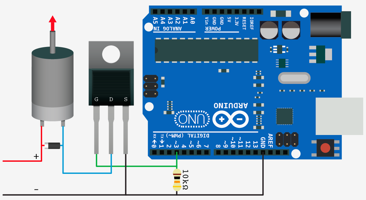 The mosfet in your kit is basically a component in support of the main actuator of your embedded systems and sensors assignment: the missing piece, a.k.a. the toilet freshener. It functions as an electronic switch, much like a transistor. The motor of the toilet freshener uses too much power to be directly connected to your microcontroller. Furthermore, the voltage level differs (1.5V for the toilet freshener, 5V for the microcontroller). The mosfet bridges these differences: the microcontroller controls the mosfet (switch) which in turn switches the toilet freshener.
Again, the example is not shown on the breadboard, but that shouldn’t be a problem for you anymore. Note that the mosfet circuit basically contains two separate parts. The primary circuit is the Stickuino / Arduino with the pin controlling the mosfet. The secondary circuit is the circuit that the mosfet is switching, containing the load (motor or toilet freshener) to be switched and an external power source, such as the battery in case of the toilet freshener. Both parts of the circuit share a common ground, i.e. the GND of both parts are connected together.
The mosfet features a gate pin which is labeled G in the image and should not be confused with GND! This is the pin that you’ll be switching using your Stickuino. Whenever you write a HIGH (1) value to this pin, the mosfet allows current to flow between the pins labeled D (= drain) and S (= source), completing the secondary circuit: the motor will start turning or the toilet freshener will turn on and release a spray-shot.
There are two more components in the circuit: a resistor and a diode. The 10k Ohm resistor functions as a pull-down resistor to make sure that the switching pin stays LOW (0), as long as there’s no clear signal on this pin (i.e. when it is floating). This may come in handy during the start-up of your Stickuino, when the pin has not yet been defined as an output. It prevents unexpected spray-shots.
Hacked toilet freshener
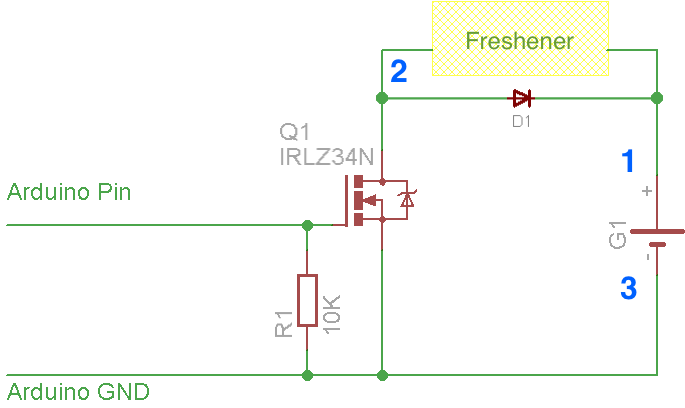
The diode is a so called flyback or snubber diode. It is mounted in reverse between the positive and negative sides of the load to be switched, blocking current flow through the diode in normal use. Although this may seem useless, it’s an important safety component that protects your mosfet: an inductive load – such as a motor – can generate a sharp rise in voltage across the current switching device if it is suddenly turned off. The diode offers an alternative current path, bypassing the mosfet.
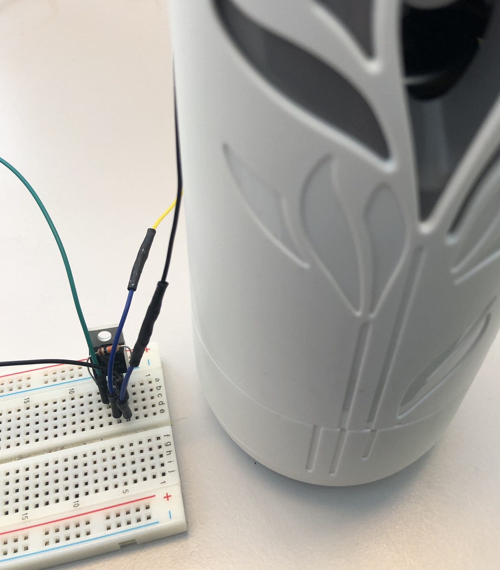
Now that the basic circuit is clear, let’s have a look at hooking up the toilet freshener. The problem is: there are no leads on the toilet freshener. That will require some hacking!
If you look closely at the schematics, you’ll see the block indicating the freshener and the battery in the secondary circuit. In fact, these are both contained in the device itself and the freshener block is actually only the electronics / motor part of it. Also, the flyback diode that is in the schematics is actually also already contained in your freshener, as part of the internal electronics, which will come in handy later on!
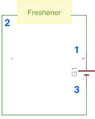
Virgin toilet freshener
Note the numbers 1, 2 and 3 in the schematics. Disregard the mosfet, diode, etc. for now. When you take the toilet freshener out of its box, the point indicated by 2 is the same point as the point indicated by 3: these two are connected together in a virgin – unmodified – toilet freshener: current flows from the positive side of the battery (point 1) through the freshener electronics / motor back into the negative side of the battery (point 2, which is also point 3).
The trick is to find this spot – i.e. the negative side of the battery – in your virgin toilet freshener and break the circuit at that spot, so that 2 and 3 are now separate points in your circuit to which you can connect the other components (mosfet, pull-down resistor, Stickuino pins), as indicated.
The mosfet, under control of your Stickuino, will then act as an electronic switch between point 2 and 3 that is normally open and can, on demand, close the circuit by connecting 2 and 3 together, causing the freshener to start working.
Normally, you’d need to identify the point indicated by 1 as well, as that’s the point where you’d normally be connecting one side of the flyback diode. Note that this point is the positive side of the battery. However, if you got hold of the latest Airwick Pure 24/7 you should leave the flyback diode – which is in your kit – out of the circuit as it is already part of the internal electronics of the freshener, saving you some work. We already said that would come in handy!
The main question now becomes: “what are the right spots and how do I hack into them?”.
It is feasible to modify your toilet freshener in a non-invasive and non-permanent, but still quite robust way by hacking into the battery compartment only, using just some wires and a bit of tape. In fact, the latest Airwick Pure 24/7 can’t be easily opened to access the internal electronics and apply the mods there, like we used to do ‘in the old days’. It would require drilling away some plastic connecting rivets and even then we found out that the electronics of the current version are not very hacker-friendly. So we’ll just do the mods on the outside of the main housing. Instructions – answering the main question – are below.
Modding the missing piece
One warning beforehand: whatever you do, don’t solder onto the batteries!
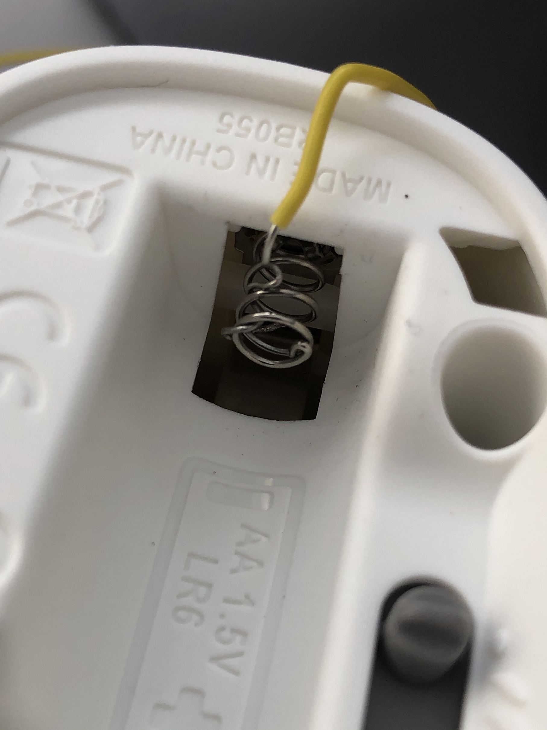
As you’ll be using your breadboard for connecting the mosfet and the pull-down resistor, and making the connections to your Stickuino, you need to bring point 2 and 3 in the schematics from your freshener to your breadboard. This is done by identifying these points in the battery compartment of your freshener, connecting wires to them and bringing these wires out to your breadboard. The first step is removing the door to the battery compartment.
Finding point 3 is now easy: it is the negative side of the battery itself. But what about point 2? Well, that is also easy enough: as we already said, in an unmodified freshener point 2 and 3 are connected together, so it is also the negative side of the battery! But, as we mentioned, we are to break point 2 and 3 apart; that is our intended mod after all. So it is better to think of point 2 as the negative side of the freshener that normally connects to the negative side of the battery. If you look at it that way, you could say that point 2 is the springy metal piece that pushes against the negative side of the battery.
Your job now is to:
- Connect a wire to the springy metal piece (point 2) and thereby bringing this point out to your breadboard. You can do this by removing the battery, cutting a length of wire (say 30 cm), stripping a few centimeters of the insulation away and wrapping that end around the springy metal a few times, so that it is securely attached. Note: you might consider soldering, but it seems the springy metal isn’t really solderable; wrapping should do as well.
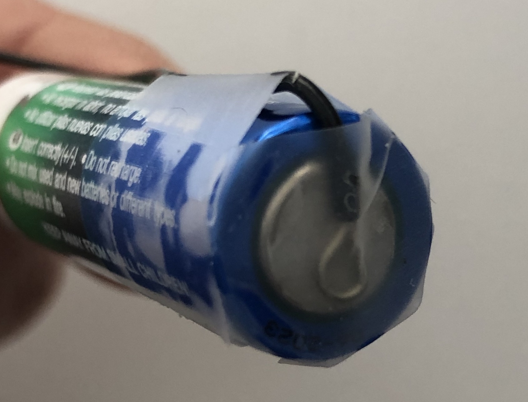
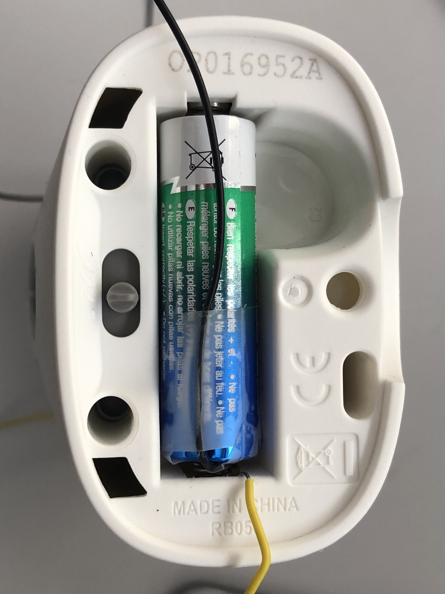
- Connect a wire to the negative side of the battery (point 3) and thereby bringing this point out to your breadboard. You can do this by removing the battery, cutting a length of wire (say 30 cm) in a different color (e.g. black), stripping just a few millimeters of the insulation away and taping that end to the negative side of the battery, so that it is securely attached. Make sure that the tape covers the full negative side of the battery, so that – when you insert the battery – point 2 and 3 are no longer connected. The tape will function as insulation between point 2 (the springy metal) and point 3 (the negative side of the battery). You might secure the wire from the battery even better by running it along and taping it to the side of the battery.
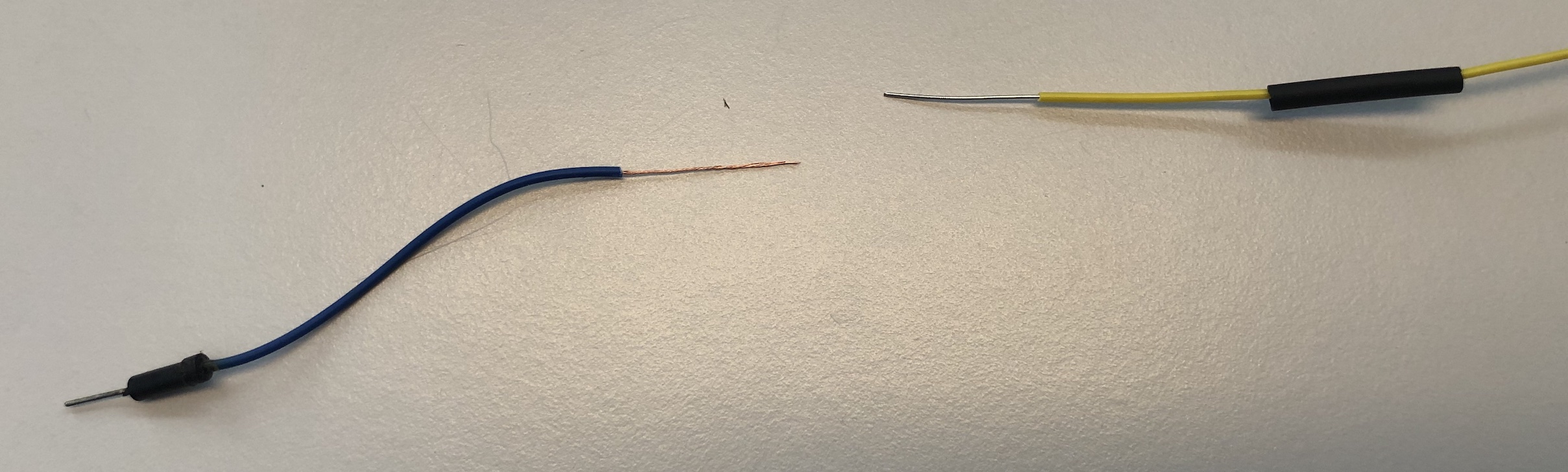
After doing this, you have two wires coming from your freshener, representing point 2 and 3 of the schematics:
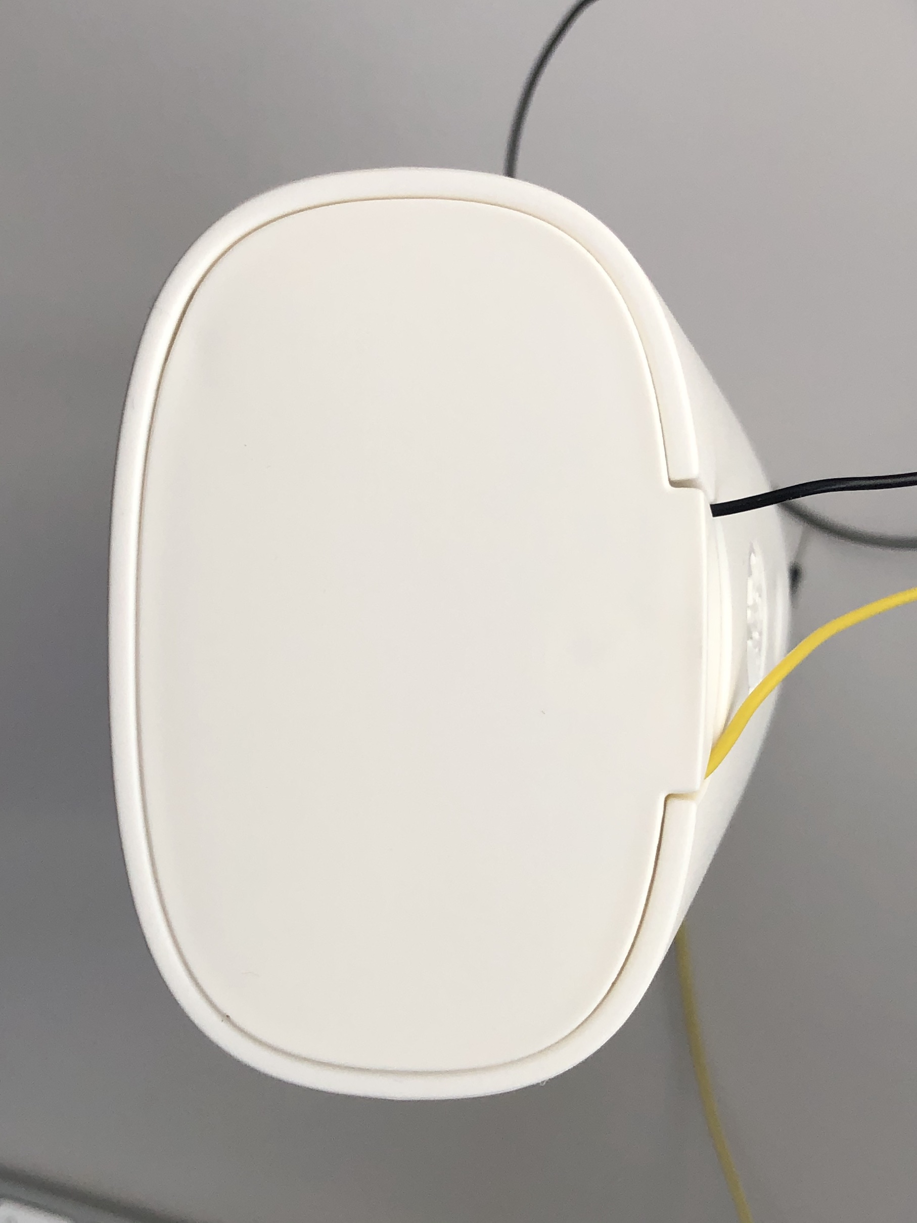
[To check whether your mod was successful, you could move the sliding switch on your toilet freshener to one of the ‘on’ positions and connect the two wires together for at least 20 ~ 25 seconds. If it sprays after ~15 seconds you did a great job.]
You may now connect these to your breadboard / the mosfet and other components to complete the circuit, as indicated in the hacked toilet freshener schematics (but without the flyback diode, as discussed). This should be doable now that you’ve come accustomed to reading schematics.
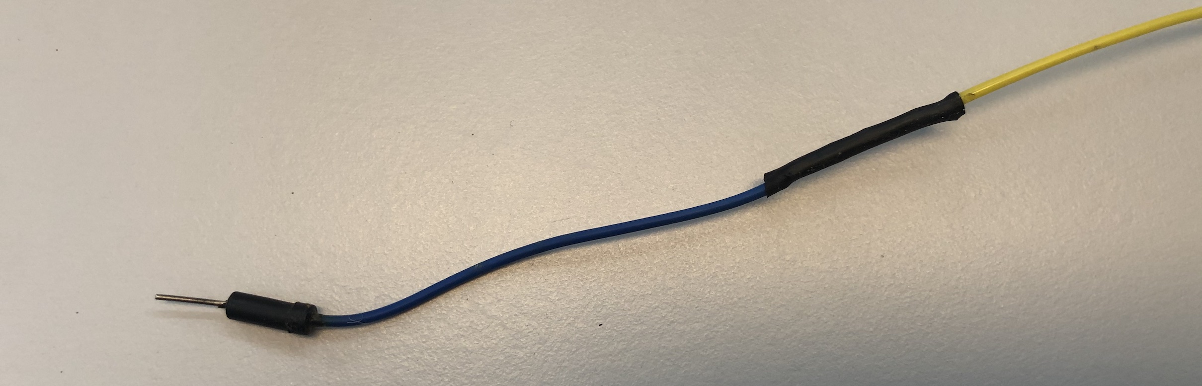
However the wires coming from your freshener might not be an ideal fit for your breadboard. That’s why we advise you to take a (short) jumper wire, cut it in half and connect each of the halves to one of the wires coming from your freshener, after stripping a centimeter or two of the insulation from both ends. You are thus lengthening each wire with half a jumper wire that will conveniently fit (and stay!) into your breadboard.
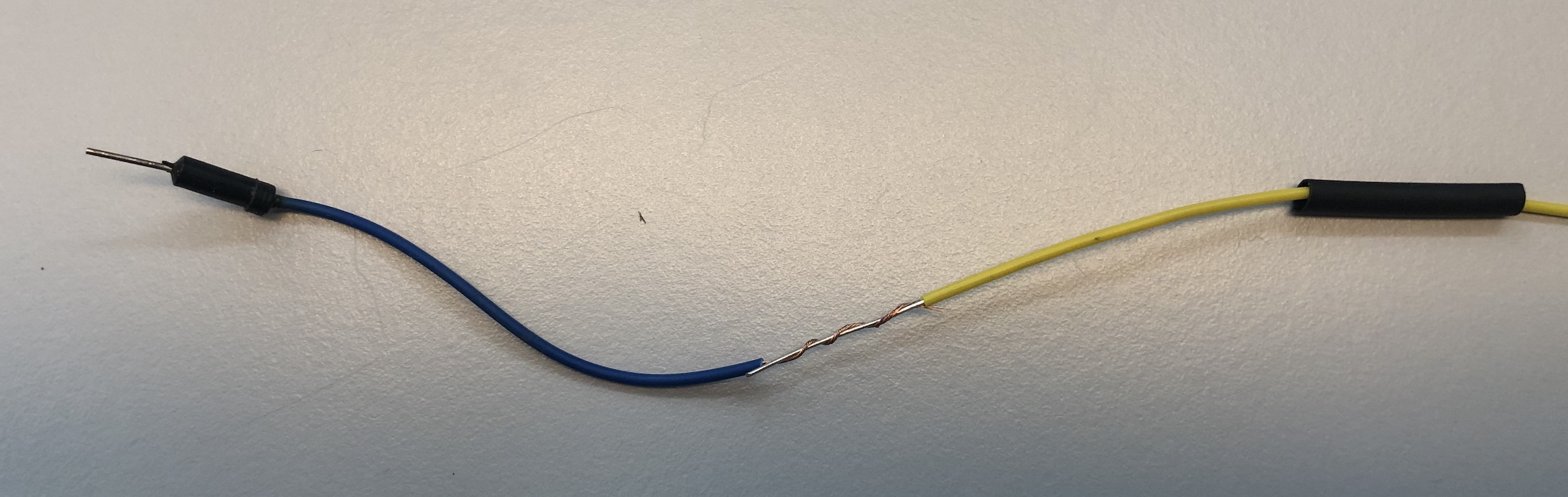
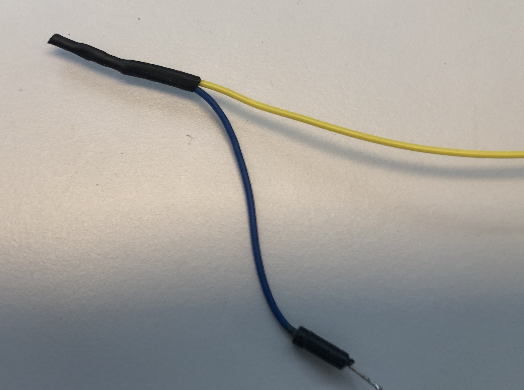
For connecting the half jumper wires to the wires from your freshener soldering would be ideal. You could even add some heat-shrink tubing (available from the Job Shop, but take only a few centimeters) to insulate the connection. If in a pinch, regular tape will also work, for insulation and maybe even for fixing the connection if you lack a soldering iron. Soldering, however, would make it much more robust.
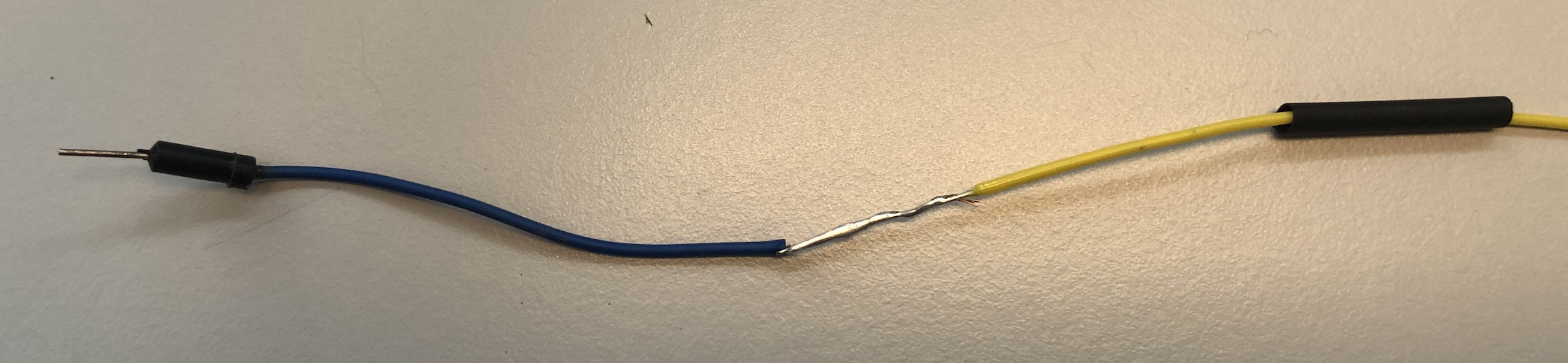
You can also use the heat of a soldering iron to let the heat-shrink tubing shrink tightly around the soldered connection, should you opt to use that. (Tip: slide the heat-shrink tubing around the wires before soldering the connection, otherwise it will be too late…) If this is not clear, just ask us when you get the heat-shrink tubing from the Job Shop.
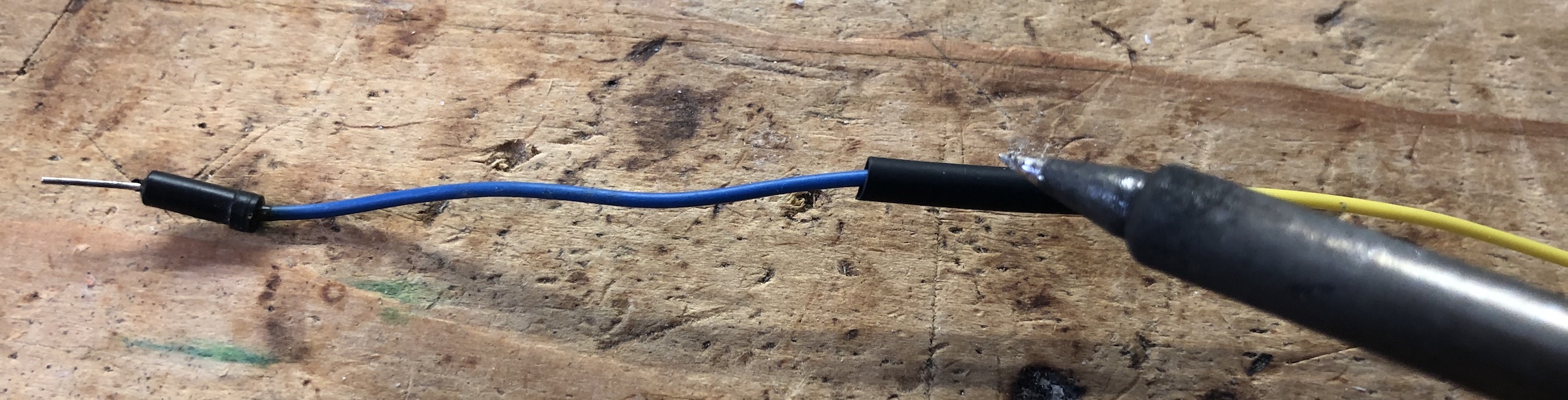
If you are lacking a soldering iron, it might be better to connect the wires and make use of the heat-shrink tubing like this, as it is probably more robust in that case:
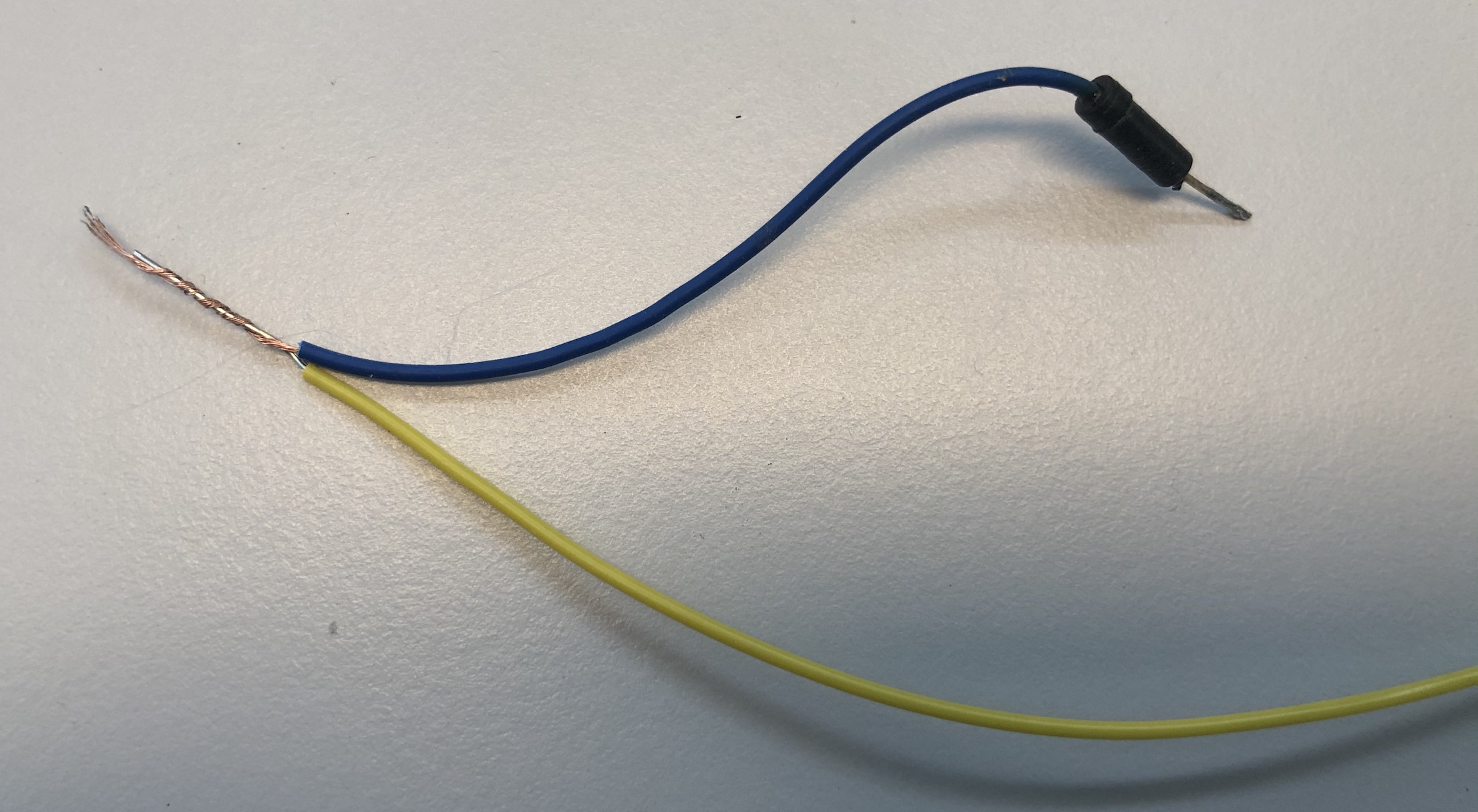
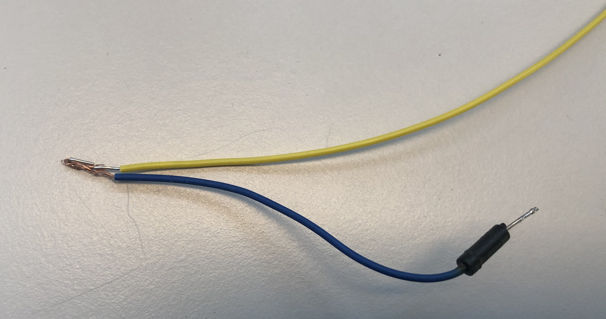
You can also use the heat of a lighter or match to make the heat-shrink tubing shrink around the joint, if you are lacking as soldering iron. But be careful: don’t set it on fire; keep the flame at a distance and use the hot air coming from the flame to shrink the heat-shrink tubing. Note that some people also use a lighter or match as an emergency wire stripper to burn away the insulation from the wires, but if you set your house on fire: we didn’t advise you to do so.
After you’ve made the necessary mods to your freshener and completed the circuit on your breadboard, you are ready to move on to the software side of things and test your circuit.
If you need more details or just want to be sure that you’re doing the right mod the right way, please make use of practical assistance. We’d be happy to help you out.
Testing your circuit
Again, if you are finding all this unclear and/or difficult, or if you are not sure about this step, please make use of practical assistance and feel free to ask. This step might look a bit intimidating at first, but try it and you’ll probably be just fine. After all, hacking stuff is what physical computing is all about!
Note that you may safely replace the toilet freshener with a led for the time being (connect the positive side to 5V and do include a 220 Ohm current limiting series resistor) while you are building and testing the circuit, if you don’t feel secure.
When you test your circuit, be very alert to any strange sound, sight or smell. Quickly remove your circuit from power if you notice anything unusual.
The sliding switch on your toilet freshener should be in one of the ‘on’ positions for the circuit to work.
From a coding point of view, the mosfet in this setup is just a binary actuator, just like a basic led: it’s either on or off. Again, have a look at the Arduino Blink example for basic control, but note that you’ll want to change the ‘on’ and ‘off’ times in this case. You need to turn it on for at least 20 ~ 25 seconds, given the approximate 15 second start-up delay of the freshener. It’s advisable to use a long ‘off’ time (or keep it off indefinitely) while testing, unless you explicitly want your device to fire more than once.
If – approximately 15 seconds after applying power to it – a heavenly cloud of goodness fills your room: congratulations, you successfully completed this task! If not, remove power and reread and recheck everything carefully. Feel free to make use of practical assistance if you can’t seem to make it work.
Beware: the motor in your freshener might make some noise as soon as the mosfet closes the circuit. This is actually the motor turning backwards a bit to make sure the spray can is currently not spraying. Don’t mistake this noise for the real deal, the spraying itself. That will only happen ~15 seconds after closing the circuit (and the spray shot will be followed by the motor turning backwards again). Test it once with the can inside of it and you will quickly find out how it works.
Here’s a video of a full operational cycle after applying power using the mosfet (click on the image):

Note the initial noise in this video after applying power, which is only the motor turning backwards (timestamp 0:05), followed by a ~15 seconds delay and, finally, the spray shot itself (timestamp 0:20).
There’s more to it
If you’ve tried all of these circuits, you’ve in fact worked with each and every sensor and actuator in your kit independently. You are now ready to start combining these circuits and writing code for your smart interactive device. Please note that although you’ve seen most of the details on the hardware side, there are still a lot of things to learn on the software side. Here are some pointers to some of these more advanced topics. These are covered to some extent during the embedded systems and sensors lectures.
- Writing non-blocking multitasking code that avoids delays.
- Using Finite State Machines in an Arduino context.
- Using interrupts.
- Debouncing inputs.
- Using EEPROM to store non-volatile values, and solving other memory issues.
- Handling millis() roll-over including a very clear explanation.
Running out of pins…
When you start combining sensors and actuators, you’ll soon notice that you need to start planning on which pin to use for which specific sensor and actuator, as not all pins are created equal (digital, analog, PWM, etc.). Remember that the Stickuino pins used for sensors and actuators may usually be reconfigured in your code if you need certain specific pins for specific sensors or actuators.
It’s usually a good idea to avoid using digital pin 0 and 1 of your Stickuino for your circuit as long as possible, as these are the RX/TX pins for serial communication and these are used for programming and communicating with your computer as well through the USB port. If you are using these pins for sensors or actuators, erratic behaviour may result when programming or using the serial monitor.
You might even find that the number of pins on the Stickuino does not match your ambition: if you want to connect every sensor and actuator in your kit (including all leds), and use two dedicated pins for serial communication, you’ll need 24 pins, where there are only 20 available.
There are, however, some techniques to save on the number of pins. Note that using these more advanced techniques is not required, as using only 2 leds (as allowed according to the requirements) will leave you needing at most 20 pins, even when using serial communication.
Advanced circuit: multiple leds on a single pin
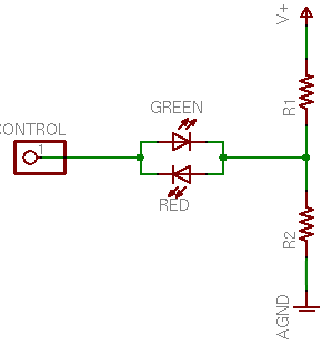 By exploiting the electronic valve property of a led, which allows current to flow through it in only one direction (remember, led = light emitting diode), it’s possible to switch 2 leds using a single Stickuino pin. See the schematics for details on how to hook this up.
By outputting LOW (0) and HIGH (1) values, you’ll able to turn either led on or off. Although it seems that you can only alternate between the leds and not have both leds on or off at the same time, that’s not the case. By quickly alternating between 0 and 1, both leds are fully controllable and even dimmable. And switching the pinmode of the pin to an input will turn both leds off.
Be sure to have a look at this blog posting (and the one that it links to) for details, if you want to use this.
Advanced circuit: multiple buttons on a single pin
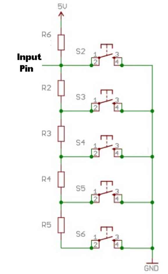 Furthermore, using a resistor ladder, it’s possible to connect several push buttons using a single Stickuino pin. This pin, however, needs to be an analog pin. Again, see the schematics for details on how to hook this up. This is just an example; you’ll probably use fewer buttons. Use 10k Ohm resistors.
Pressing a button using this circuit will create a voltage divider, with a different voltage on the analog pin depending on the specific button that’s being pressed. No button press leads to 5V or a value of around 1023 on the analog pin: the top most resistor basically functions as a pull-up resistor. Pressing the first button leads to a value of around 0 on the analog pin, as the pin is now connected to GND. The 5V supply voltage is completely burnt up by the top most 10k Ohm resistor. Pressing the second button leads to a value of about 512 as the 5V supply voltage is now equally divided between the two top most 10k Ohm resistors, each burning up 2.5V, leaving the pin to sense half of the supply voltage. Pressing the third button leads to a 1:2 voltage divider. 1/3rd of the voltage is burnt up by each of the three resistor through which the current flows, which means that 2/3rd of the voltage is still available at the input pin. The value sensed will thus be around 682. Etc.
Note that pressing the same button may not always lead to reading exactly the same value, as resistor values and voltage may vary a bit. Be prepared to accept a range of values for a certain button press.
Be sure to have a look at this tutorial for details, if you want to use this. (Unfortunately, the original page is no longer available but the Way Back Machine link should work.) The circuit is a bit different (it uses an internal pull-up resistor instead of the top most resistor), but the idea and code is basically the same.