In order to reach the objectives, the assignment is to build a smart interactive connected plant, using your Interaction technology IoT kit and a plant of your choice, adding some gesture elicitation, gesture implementation and usability testing to the mix. Your demanding task is to keep your plant alive… (At least for the duration of the assignment.)
The assignment can be divided into 3 parts or phases:
- Building your thing.
- Interfacing your thing to the outside world.
- Gesture elicitation, gesture implementation and usability testing.
These 3 parts of the assignment each have requirements of their own that are described in more detail below.
First things first
- To get a feeling for what you are dealing with, you should first try out each of the components in your IoT kit as described on the IoT platform, sensors and actuators page, before you start on the actual assignment.
- The assignment contains an SMD soldering exercise. On the IoT platform, sensors and actuators page you will come across a section describing the analog multiplexer board (AMUX board for short). This board need to be soldered the pro way, by each of the participants. Read the AMUX section to understand what needs to be done and why. Come to one of the (reservation required) AMUX soldering sessions and we’ll get you going. Don’t try this at home as this requires special equipment; a regular soldering iron won’t do.
- This assignment should again be done in pairs (unless you’re left without a partner) or teams of three (with additional requirements), as the Internet of Things will probably be new to you and there’s a lot of work to be done in a limited amount of time. Divide and conquer.
- The focus this time around will be more on software, as you’ve already built a system on a breadboard before. The second assignment is less complex from a hardware perspective. A solid hardware setup is, however, still needed as it is the foundation for your software setup.
- It may look like there are a lot of requirements, but it’s not that hard to get the basic system going. Most of it is actually quite straightforward.
- There’s also a lot of room for your own initiative and interpretation. You may do this assignment in a minimal but satisfactory way, by meeting the specifications, or elaborate on this and explore certain areas that you are interested in a bit further. Beyond the bare minimum, which is required to get a pass mark, your grade scales with the effort that you put into this assignment and your results. But be sure to first get the basics going!
Part 1: Building your thing
This phase mainly deals with connecting all the components in your IoT kit to your NodeMCU board, wiring it up to your plant, and get the basic functionality working, using libraries. You need to deal with things such as reading the pressure, temperature, light level and soil moisture level, using the AMUX board, watering your plant using the servo motor and displaying status information on the OLED screen. In short: it’s a matter of getting the hardware and software side of your system to work locally.
 As far as plants go, use any plant you fancy and/or have access to. We’d advise against cacti (cactuses) – that would feel a bit like cheating – and plants that are known to produce illegal substances. Given the time of year, why not opt for a nice spring bulb flower?
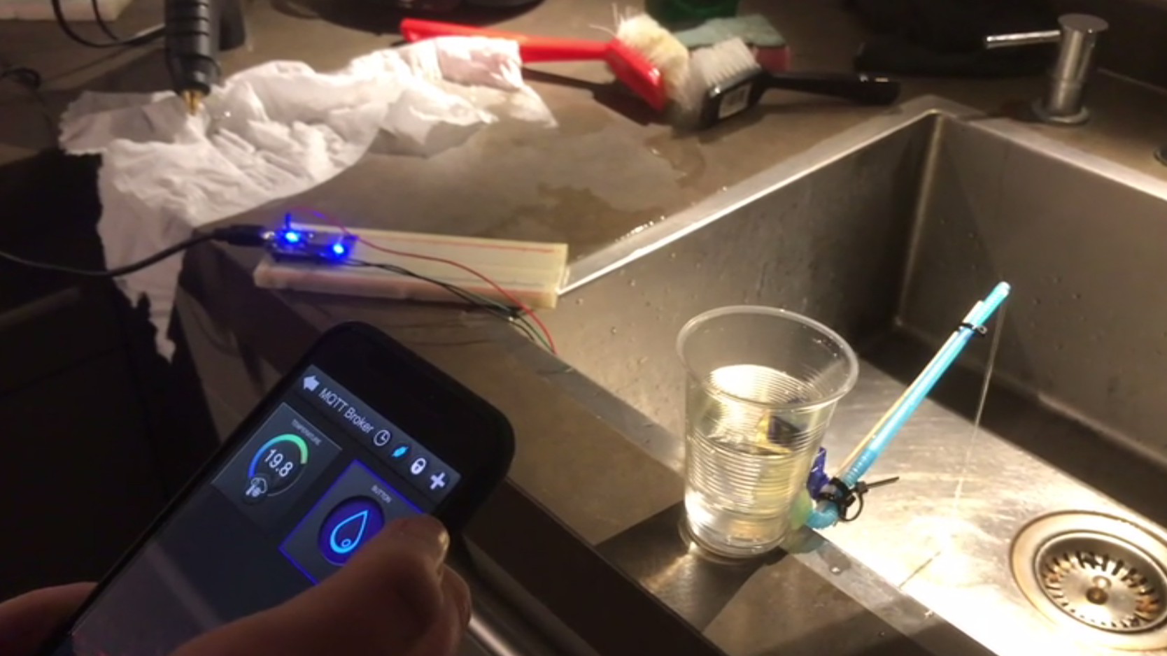
Watering the plant using the servo requires you to interface the servo to some kind of water reservoir (a 0.5 liter milk carton may do well). This probably involves lots of glue and tie-wraps. A bendy straw (the one you may remember from childhood) might come in handy as well. We have these available at the Job Shop (yes, the plastic ones, even though you can’t buy them anymore), so feel free to take one home. Be creative! You may use other means as well, as long as it works. If you need some inspiration: it has been done before. And even we built a proof of concept. Feel free to improve on this! But remember: electronics and water don’t go well together; be careful out there.
The requirements are as follows:
Hardware-technical requirements
- You need to actually build your thing. When you are working together with one fellow student, building the system once will suffice. Groups of three need to build two copies of the same system, running the same code.
- Your system must use all the components from a single IoT kit. That means that it must contain a NodeMCU board, a BMP280 pressure and temperature sensor, a soil moisture sensor (without the comparator board, as explained before), an OLED screen, a servo and an AMUX board. You are furthermore required to re-use the light sensor (LDR) from the Interaction technology sensor kit. All of these components should be functional in your thing. Note that the MPU-6050 accelerometer and gyroscope sensor should be used together with your Stickuino for gesture recognition, as mentioned below, and is not part of your IoT thing.
- You may add other components where you see fit from a single Interaction technology sensor kit, which you used during the first assignment. Obvious candidates would be the breadboard, USB cable and jumper wires, but maybe even buttons, leds and resistors could be re-used. Note that the LCD, the motion sensor and the distance sensor are a no-go, as they work on 5V and should not be connected to your 3.3V NodeMCU!
- When working together with a fellow student, you may not combine the kits to increase the number of sensors or actuators. Neither may you use any additional electronic components that were not included in the kits. You are, however, allowed to use some additional wire, duct tape, screws, card board, hot glue, tie-wraps, bendy straws and other hardware needed for mounting / installing your system.
Software-technical requirements
- Your sketch should be non-blocking and responsive. Don’t use (excessive) delays in your code that may cause you to miss certain events.
- Your sketch should be safe with regards to a roll-over of the millis() value.
- Any inputs should be correctly debounced in your sketch, whenever relevant.
- You may use any library that you see fit, including libraries for debouncing, time and scheduling related functionality, as long as you document what you are using and give credits to the original author(s). You may also adapt existing libraries to make them fit your purpose. Make sure that you comply with any licenses in doing so.
- Your code should be correctly indented, commented, split into functions, etc. like we require in our regular programming courses.
Functional requirements
- Your thing must be able to run in an automatic and a manual mode.
- Your thing should regularly read pressure, temperature, light level and soil moisture level values using the sensors, regardless of mode.
- If your thing is running in automatic mode, it should water the plant using the servo when needed, based on the soil moisture level that it reads.
- The built-in led of the NodeMCU (connected to GPIO16 or D0) should indicate whether your thing is running in automatic mode (on) or manual mode (off).
- The on-board flash button of the NodeMCU (connected to GPIO0 or D3) should toggle automatic/manual mode.
- Your thing should display the sensor values using the OLED screen. The UI should consist of a number of screens that alternate with a regular period. Each screen should show one or more sensor values.
- Your thing should clearly indicate on the OLED screen that it is about to water the plant and keep indicating this during watering.
- One of the alternating screens on the OLED display should indicate how much time has passed since the last watering.
- Your thing should prevent corrosion of the soil moisture sensor as much as possible by turning the soil moisture sensor off when no value is needed.
Note that your thing need not necessarily be very interactive to meet these requirements. A stand-alone automatic system with just the flash button for user input would do fine. For reasons of convenience and testing, it may be wise to include some more buttons and maybe leds, to force watering the plant, to force updating the sensor values, to quickly cycle through the OLED UI screens and to convey status information. This is by no means a requirement, just a very nice nice-to-have. This is Interaction technology after all.
Also note that there are a lot of things that you need to decide on, such as: how often do you read the sensor values? Is this interval the same for each sensor? What will the UI screens look like? How frequently should you alternate the UI screens? What will be the soil moisture level at which you’d say the plant is ‘thirsty’? And for how long do you water it in that case? And for how long will you refrain from watering the plant after the act to allow the water to spread? Etc., etc. Some of these things might need some experimenting (such as the amount of water and time needed to make the soil moist again or the interval for alternating UI screens) to arrive at a thing that works well and features a pleasant and intuitive UI.
Furthermore, as a way to elaborate on the basic thing that is sketched above, you may think of some improvements, additional functionalities and extensions. How about:
- …including multiple readings in determining the soil moisture level to conquer noise and improve stability?
- …a sliding carousel of UI screens instead of just appearing/disappearing screens (see the SSD1306UiDemo in the ThingPulse OLED library)?
- …finding out that the water reservoir is empty (how?), and then indicating this situation in a way that attracts human attention?
- …including the other sensors readings in deciding if and when to water the plant and for how long? (Water only by night? Water a bit more when the temperature is a bit high?)
- …tracking sensor readings for a longer period of time in order to predict when watering will be needed and showing this (continuously updated?) prediction in a UI screen?
- …adding buttons and leds to force watering the plant, to force updating the sensor values, to quickly cycle through the OLED UI screens and to convey status information, as mentioned before?
Again, these are just lines of thought. None of these are required. Some of these may be quick-wins though. And there may be other improvements, functionalities and extensions that you may think of yourself. If you are working in a group of three we would expect you to implement some of these to show you put in the extra hours available to your group.
As in assignment 1, a bonus will be awarded to anyone who creates a neat physical device. For this, you may once more make use of the facilities in Lili’s Proto Lab, our own makerspace, such as the 3D printers, laser cutter, CNC, vacuum former, etc. Feel free to discuss the options with the lecturer of the IoT topic. Again, this is fully optional.
Part 2: Interfacing your thing to the outside world
This phase mainly deals with connecting your thing to the internet, and use the MQTT protocol to send/receive sensor values and commands. For this to work, you need to work with an MQTT broker. You should also set up a number of MQTT clients on different platforms to process sensor data and issue commands. You need to deal with MQTT specific aspects such as topics, QoS, retained values, etc. as well as more general connectivity issues, such as WiFi configuration and maybe security. Then there’s the matter of building an IoT platform, which involves control and visualization. In short: it’s a matter of getting the hardware and (especially) software side of your system to work remotely.
Before you start, read up on MQTT using the MQTT essentials series. Scroll down the page till you find the heading MQTT Basics (just under the video). Start with part 1 and work your way through all 12 parts we selected. You should also read 6 parts of the MQTT security fundamentals series. Links to these series and the specific parts that you should read are available from the literature and support page.
The requirements are as follows:
Hardware-technical requirements
- The hardware-technical requirements from part 1 stay in place.
Software-technical requirements
- The software-technical requirements from part 1 stay in place.
- You should use a Mosquitto MQTT broker. This must be either the Utrecht University Faculty of Science MQTT broker that is running at mqtt.uu.nl or a Mosquitto installation hosted on your own server. We strongly advise you to use the Utrecht University Faculty of Science MQTT broker as it will save you a lot of time (unless you are really interested in setting up and hosting your own server; Docker might come in handy in this case). Also: it needs to be up and running at all times, which comes automatically in the case of the Utrecht University Faculty of Science MQTT broker.
- You should install a diagnostic MQTT client and use it to connect to the MQTT broker. This must be either MQTT Explorer, mqtt-spy or MQTT.fx. Note that MQTT.fx is now a commercial product, but you could request a free trial indicating that you are a student wanting to learn about the technology. Older – free – versions may also still float around. MQTT Explorer seems to work nicely though, also on Linux.
- You should install Node-RED (which requires Node.js), and use it to connect to the MQTT broker for flow-based control and visualization.
- You should install an MQTT app on your phone that allows you to build a UI, and use it to connect to the MQTT broker for control and visualization. We’ve had success with free apps such as IoT MQTT Panel (available for Android, as well as IoS). Other suggestions are welcome! If IoT MQTT Panel doesn’t work for you and you really can’t find a suitable free app for your phone platform, feel free to use the Node-RED dashboard plugin to build your UI and use your phone’s web browser.
- Your thing should use an MQTT library to connect to the MQTT broker for sending/receiving sensor values and commands. This must be either the MQTT PubSubClient library by knolleary or the Adafruit MQTT library. These libraries (and possible dependencies) can be installed using the Library Manager in the Arduino IDE. These libraries require you to use the ESP8266WiFi library that’s included with the ESP8266 Arduino core to connect your thing to the internet.
If you opted to use the Utrecht University Faculty of Science MQTT broker, which we highly recommend, you’ll need some credentials to be able to connect to it. Your MQTT username and password for this broker can be found in the Brightspace course environment under Grades. Your username is of the form studentXXX, with XXX being a number, e.g. student042.
With these credentials you should be able to publish and subscribe to the infob3it/studentXXX topic – with XXX being the number from your username – on the Utrecht University Faculty of Science MQTT broker, and any topic below this level that you may choose to define; e.g. student042 should have read/write access to topic infob3it/student042 and – for example – infob3it/student042/temperature. You won’t have read nor write access to topics of other users. Note that there is no leading slash in the topic infob3it/studentXXX, as explained during the lectures on the Internet of Things.
It’s a good idea to implement the MQTT part one client at a time. Start with the diagnostic client to check whether you can connect to the MQTT broker using your credentials and have read/write access to your topic(s), then add your thing, etc.
An important choice concerns the MQTT library you are going to use on your NodeMCU. The MQTT PubSubClient library by knolleary and the Adafruit MQTT library are similar in the sense that they both allow you to connect to a generic MQTT server, but there are some important differences:
The MQTT PubSubClient library by knolleary is more straightforward to use, as it assumes a generic MQTT server, such as Mosquitto / mqtt.uu.nl out of the box. It comes with an mqtt_esp8266 example to get you going. It also seems to be the more popular MQTT library. It does however have some limitations, the most important one being that it can only publish QoS 0 messages. It can subscribe at QoS 0 or QoS 1. Furthermore, this library does not supply an example using SSL/TLS encryption out of the box, although the adafruitio_secure_esp8266 example from the Adafruit MQTT library using the WiFiClientSecure client may be adapted to use the MQTT PubSubClient library by knolleary. Note: the Utrecht University Faculty of Science MQTT broker does not yet support SSL/TLS connections, so this is somewhat academic at this time.
Although the Adafruit MQTT library may have more features, such as publishing and subscribing at QoS 0 and Qos 1 (not QoS 2 though), and offers an example using SSL/TLS encryption, it is geared more towards Adafruit’s own IoT platform Adafruit IO. Topic names and authentication in the examples often assume that you’re using Adafruit IO. As long as you understand that ‘key’ means the same as ‘password’ in many of the examples, ‘feed’ is sometimes used instead of ‘topic’ and that you are not required to use the rigid topic structure that Adafruit IO uses when connecting to our own MQTT broker, you should be fine. The mqtt_arbitraty_data example shows that a generic MQTT broker is certainly an option.
If the library you choose does not support the functionality that you would have wanted to use (such as QoS levels, etc.), you should document this and indicate how you would have wanted to use it (such as the actual QoS level of each topics versus the intended QoS level of each topic).
Functional requirements
- The functional requirements from part 1 stay in place.
- All connections to the MQTT broker should require a username and password.
- Your thing should connect to the MQTT broker on startup.
- Your thing should regularly publish pressure, temperature, light level and soil moisture level values in separate topics.
- Your thing should subscribe to a topic that is used to send it a command to water the plant.
- Your thing should subscribe to a topic that is used to send it a command to immediately read new sensor values for all sensors and publish these in their respective topics.
- Your thing should publish and subscribe to a topic that is in sync with the mode that your thing is running in (automatic/manual).
- Your thing should use the Last Will and Testament feature in combination with the Retain flag to indicate its online status in a dedicated topic, as explained in part 9 of the MQTT essentials series.
- Your thing should offer some form of robustness when it loses its connection, such as reconnecting and resubscribing (potentially using persistent sessions).
- You should use your diagnostic MQTT client to monitor the MQTT traffic to and from the MQTT broker. You should also use it to test the functionality of your thing.
- You should use Node-RED to create a flow that connects to the MQTT broker and subscribes and publishes to a number of MQTT topics. You should use a Node-RED dashboard to visualize sensor values using gauges and graphs, and to issue commands to water the plant, update the sensor values and control and monitor automatic/manual mode. You should also show the online status of your thing in the dashboard. You may use any Node-RED plugin, as long as you give credit.
- You should use the MQTT app on your phone to build a UI to visualize some of the sensor values, and to issue commands to water the plant and update the sensor values. The UI should also allow you to toggle and monitor automatic/manual mode. If you really can’t find a suitable app, you may use a Node-RED dashboard for this, as explained before. In that case, however, you should create a separate dashboard with dedicated UI screens for your phone.
Again, there’s a lot of room for your own interpretation. You need to decide on the details, such as topic structure, payload format, required QoS levels, retain flags, publishing frequency, etc. Also, there are no requirements concerning quite important aspects, such as:
- Initial configuration. Are you going to hardcode the SSID and key of your home WiFi network in your sketch? Or are there better ways to do the initial configuration? One option would be to switch to Access Point mode with a captive portal if the configured network (stored in EEPROM) is not available. There’s a library for that.
- Security. Will you be using SSL/TLS using the WiFiClientSecure client or will you be sending everything in plain text, including usernames and passwords? Note: as the Utrecht University Faculty of Science MQTT broker does not yet support SSL/TLS connections, implementing this is currently not an option if you opted for that broker, but you might reflect on this in your report.
- Over The Air (OTA) updates. Will you support updating your thing from the Arduino IDE in a wireless fashion? It may sound complex but again there’s a library for that.
- Rule based control. The Node-RED flow could contain rules that water the plant automatically based on received sensor values. In that case, you would also have to make sure that this would not conflict with local decisions.
- Additional MQTT functionality. If you have extended your thing with additional components such as buttons and/or leds, you might want to read or control these remotely as well. And maybe you want to use MQTT itself to configure your device (topics for configuration).
Again, none of these are part of the requirements. However, if you are looking for areas to improve your system in, these would be likely candidates. Even if you won’t be implementing these, you might give them some thought and document how these things would be used in and be beneficial to your system. We might then decide that that would be beneficial to your grade. Again, if you are in a team of three, this is where you could/should shine!
Part 3: Gesture elicitation, gesture implementation and usability testing
In this phase you’ll extend your system with a new interaction paradigm: gestures, using an accelerometer and gyroscope sensor. The goal is to design and implement a setup for your Stickuino – yes, the one from the first assignment – that reads the accelerometer and gyroscope sensor, recognizes gestures and interfaces with your IoT platform to control your thing.
However, in this part the focus is less on the technical aspects of your solution (hardware, software) and more on the empirical aspects.
There are three main requirements in this phase:
1) Gesture elicitation. You are required to do a gesture elicitation study with approximately 5 people (see below for the meaning of “approximately 5”) to determine the gesture set needed to execute two actions:
- Watering the plant
- Retrieving sensor values
In this study, participants are individually shown the desired effect of an action (called a referent) and asked to propose the gesture (called symbol) that would bring that effect about. The results from all participants are then reconciled to create a single gesture set, possibly including synonyms, using metrics such as agreement rate.
2) Gesture implementation. After identifying the gesture set, you are required to implement it using your Stickuino and your MPU-6050 accelerometer and gyroscope sensor.
3) Usability testing. You are required to do usability testing on the system and the gesture set with the same participants as the gesture elicitation. The study setup can be:
-
- in person/remote,
- moderated/unmoderated,
- concurrent probing/retrospective probing,
- concurrent think aloud/retrospective think aloud
This usability testing will help you to ascertain whether the gesture set from the elicitation study is as effective as expected at executing the two referents. It helps uncovering limitations and possible ways to improve the interaction with the system.
STEP-BY-STEP GUIDE
To guide you, here’s a step-by-step guide to complete the three requirements of this third phase: (a) gesture elicitation, b) gesture implementation, c) usability testing.
Part 3a: Gesture elicitation
- Prepare: Define your referents (actions) and structure your gesture elicitation study. Make sure you have a plan before you recruit participants. Think how many gestures you will ask your users to produce for each referent.
- Recruit: Recruit approximately 5 people for your study. (This is an indicative number. If you struggle to find 5 participants, it is ok to have fewer.)
- Run: Conduct the elicitation.
- Analyze: Calculate agreement scores (see slides) and define your final gesture set.
- Report: Report the elicitation study in the report in a narrative form.
Part 3b: gesture implementation
Next, proceed to implement your gesture set in such a way that you meet the following requirements:
Hardware-technical requirements
- The hardware-technical requirements from part 1 and 2 stay in place.
- You should use your Stickuino and your MPU-6050 accelerometer and gyroscope sensor for gesture recognition.
- To interface your Stickuino with your IoT platform, you should keep it always connected to a computer, using its USB interface. This means you’ll also need your USB FTDI serial adapter board.
- Your Stickuino and the accelerometer and gyroscope sensor should be mounted to your body. We leave the how and where up to you. Note that a nice (3D-printed?) mounting option or housing may once more lead to a bonus.
Software-technical requirements
- The software-technical requirements from part 1 and 2 stay in place.
- You are allowed to use software from third parties. Again, you may use any library, as long as you give credit.
- To interface your gesture recognition setup with your IoT platform, you should use Node-RED.
Functional requirements
- The functional requirements from part 1 and 2 stay in place.
- Your gesture recognition setup should recognize a watering gesture. Upon recognizing this gesture your gesture recognition setup should communicate this fact to your Node-RED flow, leading to the watering of your plant.
- Your gesture recognition setup should recognize a sensor retrieval gesture. Again, upon recognizing this gesture your gesture recognition setup should communicate this fact to your Node-RED flow, leading to an immediate update of the sensor values.
- Gesture recognition should take place locally on your Stickuino, not on the computer it is connected to. Simple procedural signal processing (i.e., a sequence of states) will do. There’s no need for advanced filtering techniques, such as a Kalman filter. For inspiration and tips, check out this video. Note that the code doesn’t seem to be functional anymore, but you need to write your own code anyway. It’s still an interesting example to have a look at. (But don’t interpret that as ‘I need to get this example code running!’) Furthermore, note that graphing the sensor output is not a requirement in this assignment, but it might be beneficial to try out graphing the data to understand the sensor output for certain gestures. If you want to graph the sensor output – again, not required – you could use the Serial Plotter that is part of the Arduino IDE for this, which is quite easy to get working. Also note that the example in the video only uses the accelerometer, not the gyroscope. If this will do for your setup, that is fine.
- Interfacing your gesture recognition setup with Node-RED should be done using Serial communication, through the USB interface. There are several more or less advanced ways to achieve this, but a simple Serial connection may be enough. In fact, communicating just a simple bit to indicate that a certain gesture has been recognized will do. You may use any Node-RED plugin, as long as you give credit.
Feel free to add functionality, use the gyroscope, expand the repertoire of gestures, etc., as long as the input is based on local gesture recognition using the MPU-6050 accelerometer and gyroscope sensor.
Part 3c: Usability testing
- Prepare: Define your usability study design (in person/remote, moderated, unmoderated, etc.) including the measures (e.g., time on task, reported efficiency, reported errors, reported learnability, user satisfaction, etc.)
- Recruit: Follow up with the participants from the elicitation study and ask them to partake in this final stage of the system evaluation.
- Run: Conduct the usability testing.
- Analyze: Gather insights from the data gathered in the usability study.
- Report: Report the usability study in the report in a narrative form.
This concludes the requirements of the second assignment.
Questions? Problems? Don’t know where to start?
As always, feel free to ask questions! Contact your TA and/or visit an on-campus practical session if you need help. Also, check out the deliverables for this assignment, so that you know what’s expected from you.