This page is here for students who followed the course in 2020/2021 or earlier. In these years – before we were hit by the global component shortage – the hardware kit featured a BME280 instead of the current BMP280. The main difference is that the BME280 features a humidity sensor on top of the pressure and temperature sensor.
The instructions below apply only to the BME280 and NOT the BMP280.
1 * Pressure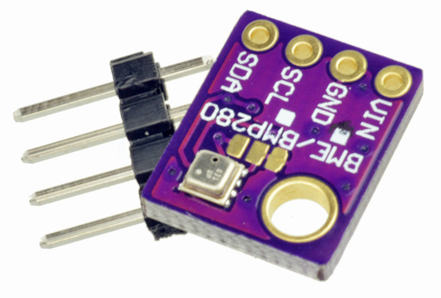 , temperature and humidity sensor, BME280, including header strip, male, straight, 4 pins. This quite advanced digital sensor uses the I2C protocol to provide pressure, temperature and humidity readings. And if calibrated for sea level pressure it will even provide altitude readings based on pressure, but as the assignment does not include vertical gardens, nor flying plants, we won’t go down that path.
The BME280 features actually three sensors in a very tiny package and is mounted on a small board containing some supportive hardware. Connecting it is straightforward: supply 3.3V and GND to the supply pins and connect the two remaining pins to the I/O pins of your NodeMCU.
 The I2C protocol is a bus protocol. That means that multiple devices may share the two I2C data lines. To be more precise: what we loosely call the ‘data’ lines are in fact one real data line (often called SDA) and one clock line (often called SCK or SCL). You’ll often see those names printed near the pins of I2C devices.
Each I2C device has its own address and the I2C protocol takes care of sending commands to and reading values from the correct device using its address. The Wire library (not to be confused with the OneWire library) is the library that takes care of the I2C protocol. The ESP8266 version of the Wire library is included with the ESP8266 Arduino core. On top of that, a library is needed for each device type that takes care of the device specific I2C commands (sending data, reading values).
For the BME280 sensor you may use the Adafruit BME280 library. Using the Adafruit BME280 library will require you to also install the Adafruit Unified Sensor library. There’s an example named bme280test included in the Adafruit BME280 library to get you going.
However, there’s a catch: the BME280 sensor in your kit listens to I2C address 0x76, as opposed to the libraries default address 0x77. As indicated in the bme280test example it is possible to pass the address as an argument to the begin() function call of the BME280 sensor, e.g. status = bme280.begin(0x76);
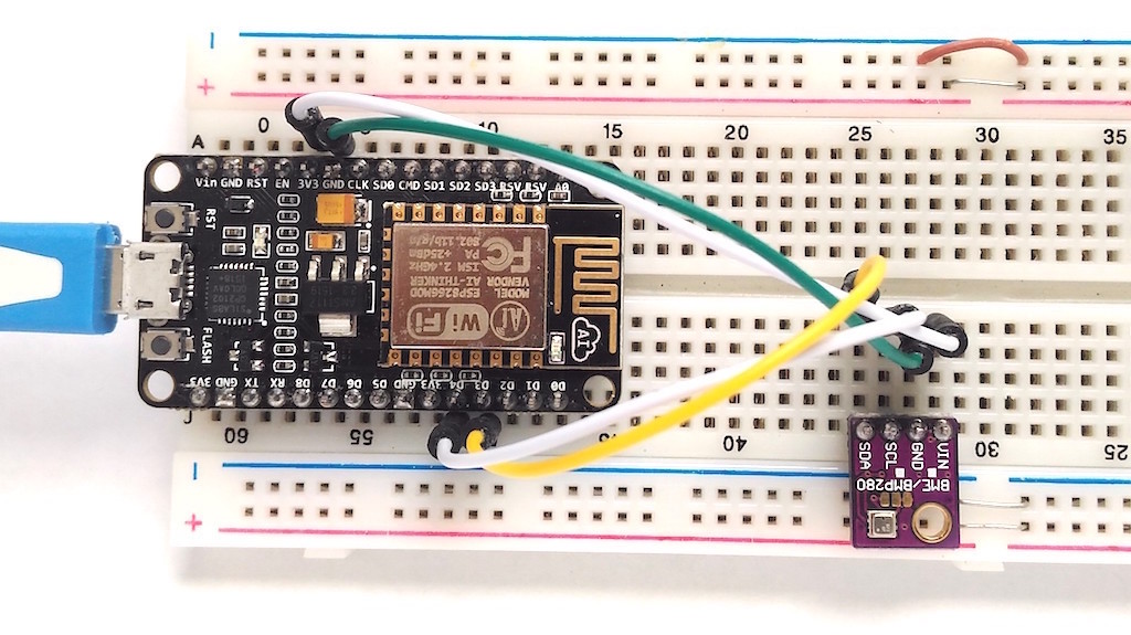
Furthermore, on the ESP8266, you might need to specify which pins you’re using for I2C. The default pins that the Wire library uses are D2 for SDA and D1 for SCL. If you use these defaults, you won’t need to specify these, nor initiate the Wire library, as this is all taken care of by the BME280 library.
If, however, you want to use different pins for I2C, use Wire.begin(SDA_PIN, SCL_PIN) with the appropriate pins in your setup function before you start the BME280 sensor using its begin() function call. It has successfully been tested using Wire.begin(D3, D5), but other pins may be used as well, such as in picture where D3 and D4 are being used.
Regardless of the pins you are using, there’s no need to pass a Wire object as a second argument to the begin() function call of the BME280 sensor, as the library defaults to &Wire, being the standard Wire object that we are using.
Finally, as we are using I2C, you can get rid of the #include <SPI.h> line in the example that includes the SPI library, a totally different protocol for talking to sensors that is unneeded ballast in this case.
If you (really) want, you may also use any alternative BME280 library, but in that case you’ll be on your own to get it working.
Oh, one more thing. You’ll need to solder headers onto the board before you’ll be able to use it… For convenience, make sure that you solder it in such a way that the sensor itself (a single tiny silver square component on one side of the board, as shown in the pictures) is on the top side when you put the board in your breadboard. In that way you’ll be able to read the pin labels while the board is inserted into your breadboard. Excess pins, if any, may be broken off.