On this page, we take a more detailed look at the contents of the Interaction technology IoT kit, to gain a basic understanding of the platform you are using and the components that are included. This page assumes that you are familiar with the sensors, actuators and the supportive components in your Interaction technology sensor kit, which you used during the first assignment.
Included in the description of each of the components in your IoT kit is a primer on how to connect it. Again, don’t expect full tutorials, extensive walkthroughs or code examples. Although you’re working with another platform now, it’s still all about experimenting and learning from what’s already been done.
We suggest that for starters you first go through all of this and actually build the individual circuits. Try out each of these components before you start on the actual assignment and unleash the complexity of combining things.
ALWAYS DISCONNECT YOUR NODEMCU FROM POWER WHEN BUILDING/MODIFYING YOUR CIRCUITS!
The NodeMCU ESP8266 development board is much less forgiving than your Stickuino: wrong voltages, misplaced wires, etc. can easily kill it. Please make sure that you follow the instructions and look twice before you apply power to your circuits!
Microcontroller
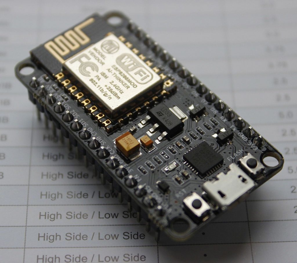 1 * NodeMCU ESP8266 development board, V1.0. This microcontroller board is the ‘heart and brains’ of your IoT kit. It is very comparable to your Stickuino board in function, which by now you are very familiar with. However, there are some important differences. First of all, it is much more powerful, offering a 32-bit ESP8266 microcontroller (mounted on an ESP-12E module) with a whopping 80Kb of RAM memory as well as 4Mb of flash memory. Also, the form-factor is different: this board will (and must) directly fit into your breadboard. Last but not least, the ESP8266 microcontroller features a full WiFI stack, which enables you to connect to the Internet.
The neat thing is that there’s an Arduino core for the ESP8266 that allows you – if installed – to use the NodeMCU board with the Arduino IDE, just like your Stickuino. A lot of code and libraries will run on both boards with only minor adaptation. Full documentation for the ESP8266 Arduino core including a function reference as well as installation instructions is available on the ESP8266 Arduino core documentation page. Development of the ESP8266 Arduino core takes place on GitHub, should you be interested. Make sure that you install it using the Boards Manager method.
The original NodeMCU comes with the Lua based NodeMCU firmware. We won’t be using that but will use the Arduino core instead (C/C++). For your convenience, Blink is already installed on your NodeMCU, so you should see a merry-blink-around if you connect it to power through USB.
 As explained during the towards assignment 2 lecture, the NodeMCU board contains a USB serial adapter chip, whose function is similar to that of the red USB FTDI serial adapter board in your Interaction technology kit: enabling you to connect the board to your computer and program it. However, the specific chip is from a different manufacturer. The chip is a CH9102X by WCH. To be able to connect to your NodeMCU board and program it, you should have the correct drivers for this chip installed. These are available from the WCH website, should they not be available on your system yet or should they not install automatically. Adafruit has published a convenient tutorial with “how to install” instructions for Windows and macOS.
[Note: if you participated in this course in a previous year, your NodeMCU will feature a CP2102 chip by Silicon Labs. If you still need drivers for that chip, just search for “Silicon Labs CP2102 drivers” in your favorite search engine and you’ll end up on the download page of the Silicon Labs website.]
After installing the ESP8266 Arduino core and the drivers, be sure to select the correct board from the Tools->Board->ESP8266 dropdown (NodeMCU 1.0 (ESP-12E Module)), and select the correct port from the Tools->Port menu in the Arduino IDE.
The ESP8266 Arduino core contains a number of examples, with the more interesting ones being the ones using the included ESP8266WiFi library, as these allow you to connect to the Internet. Go ahead, and see if you can make your NodeMCU connect to your home WiFi network and acts as a webclient and webserver, have it scan for WiFi networks, etc.
In general, there’s a lot of information on the NodeMCU / ESP8266 platform available on the Interwebs, including tutorials and the pin-out. Just do a search and you should be fine. Also make sure that you have a look at the slides introducing the ESP8266 platform, as presented during the towards assignment 2 lecture, as it provides some important details.
To prevent mishaps, a few words of caution are in place:
- There are also some other versions of the NodeMCU board out there. These may have different – less convenient – form factors and – more importantly – feature a different USB serial adapter chip (the CP2102, to be more precise). Don’t install CP2102 drivers (unless you participated in a previous year), but do install CH9102X drivers if needed.
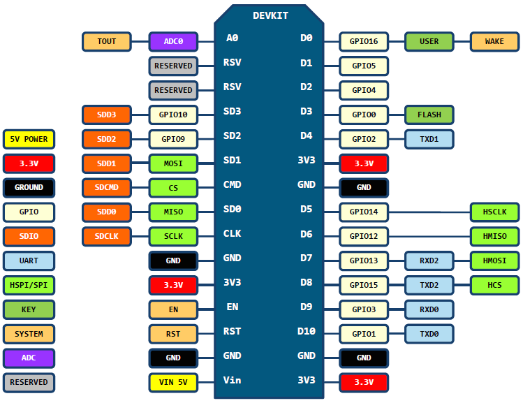
- There’s a difference between the pin numbers on the ESP8266 and the pin numbers on the NodeMCU board. For example: if you use digitalWrite(2, HIGH) you are controlling GPIO pin 2 on the ESP8266 which happens to translate to pin D4 on the NodeMCU board… See the pin-out of the NodeMCU v1.0 board to map GPIO pins to NodeMCU pins. Even better: you may directly use the NodeMCU numbering scheme in your sketch. The example above, to control NodeMCU pin D4, could then be rewritten to digitalWrite(D4, HIGH) for the equivalent operation, which is semantically much more meaningful. We strongly suggest using the NodeMCU numbering scheme if possible for reasons of convenience and clarity.
- Although it seems that a lot of pins are available, some pins have special functions or are connected to internal components of the ESP8266 module making them unavailable as general purpose I/O pins. Examples of these pins are GPIO3/D9 and GPIO1/D10. These are the RX and TX pins for serial communication that are used for programming your board. Other examples would be GPIO16/D0 (LED) and GPIO0/D3 (flash button). And then some. Check out this Reddit and this Google sheet if you want to know the gory details. The Google sheet includes recommendations for pins to use for sensors but be aware that it refers to the ESP8266 chip itself – not the NodeMCU board – and uses the GPIO numbering scheme. Note that you don’t need that many general purpose I/O pins for the second assignment, so you should be fine.
- Always make sure that any information you use from the internet concerning the NodeMCU pertains to the V1.0 version that you have (and not the V0.9, V2, V3, V-whatever version) using the Arduino core (and not the Lua based NodeMCU firmware).
- The ESP8266 runs a lot of utility functions to keep WiFi connected and manage the TCP/IP stack. These are added to your code automagically upon compilation of your sketch. These functions must be serviced regularly and usually servicing is done implicitly with each iteration of the program loop, calls to the ESP8266 library functions and even whenever you call the delay function (which you shouldn’t 🙂 ). Still, you’re dealing with a single threaded microcontroller, and if implicit servicing isn’t happening in due time, the so called watchdog timer kicks in: the watchdogs thinks that your sketch is hanging and issues a reset. If you see spontaneous resets that you can’t explain, this might very well be the reason. Prevent long running code that blocks implicit servicing (e.g. by not going through the program loop regularly) and if you really have to, use the yield function at regular intervals to request explicit servicing. The ESP8266 Arduino core documentation has a section on spontaneous resets as it may be one of the bugs that bites you regularly.
- The NodeMCU / ESP8266 platform uses 3.3V instead of the 5V that you are familiar with from the Arduino / Stickuino world. NEVER supply 5V to its pins, either directly or through a 5V sensor or module, as you will damage your board. In general: don’t connect components that you used during the first assignment to your NodeMCU unless instructed otherwise. To be more specific: don’t connect the motion sensor, distance sensor or the 16×2 LCD from your Interaction technology kit to the NodeMCU. The other components – buttons, leds, light sensor (LDR) and temperature sensor (DS18B20) – are fine, as long as they are fed with 3.3V supply voltage. Read up on the platform first, to make sure that you know what you are dealing with. If in doubt, feel free to ask for help during the practical sessions.
- The 3.3V versus 5V incompatibility also holds the other way around: don’t connect the sensors / actuators from the second assignment (the ones that came with the NodeMCU) to your Stickuino unless instructed otherwise, as most of these are not 5V tolerant.
- Don’t connect anything to the VIN pin of the NodeMCU. This is the Voltage IN pin, which is equal to 5V when connected to USB, and as already discussed 5V is a no-go on this platform.
Did we already mention that you should read up on the platform first?
Sensors
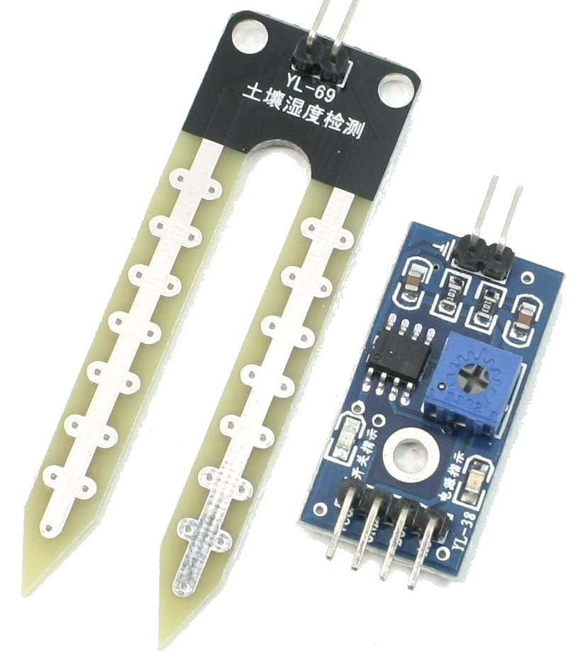 1 * Soil moisture sensor, including wires and LM393 comparator board. As its name indicates, this sensor is used to determine the moisture level of soil. The two pins – but not the base – of the sensor should be fully inserted into the soil.
Its function is based on resistance, which is quite straightforward: a voltage is applied across the pins and if the soil is dry, the resistance between the pins will be high (potentially even infinite if held out of the soil in dry air). If, however, the soil is wet, the resistance between the pins will be low (potentially even zero if inserted into a conducting fluid). And if the soil is not dry as dust and neither soaking wet, the resistance will just vary according the moisture level.
It’s an analog sensor that provides an analog resistance value and, as you should know by now, it will take a voltage divider to turn the variable resistance into a variable voltage that you can read directly with your NodeMCU board. But more on that later, as things may be more convenient than you’d expect. Reading the analog value is not different from reading, let’s say, the analog value of an LDR (light depending resistor), as done in the first assignment.
The soil moisture sensor comes with a comparator board which can be used to turn the analog reading into a digital one (providing a HIGH/LOW output) by setting a threshold value using the blue variable resistor on the comparator board. The LM393 comparator chip on the comparator board compares the resistance value of the variable resistor (i.e. the threshold value) to the resistance of the soil moisture sensor and outputs HIGH (wet) or LOW (dry) accordingly, indicated by an on board led. The output of the comparator chip is available on the digital output (D0) of the comparator board, turning it into a binary sensor that can be read using one of the I/O pins of your NodeMCU.
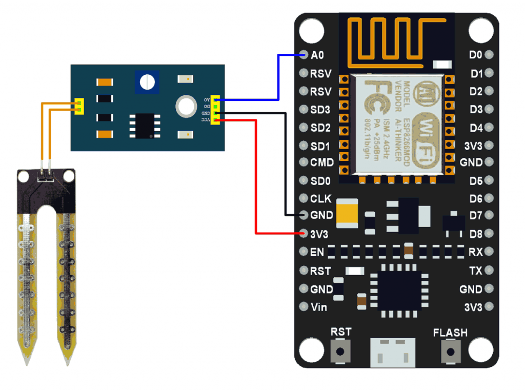 The comparator board also provides an analog output (A0). If you connect this to the A0 analog pin of your NodeMCU, you won’t need a voltage divider, as it is already included on the comparator board, and you should be able to directly read analog values.
Also included are some female-to-female jumper wires, which will help you to conveniently connect the soil moisture sensor to the comparator board.
You can put the comparator board aside after testing, as we won’t be using this board during the second assignment. You’ll just use the soil moisture sensor itself. This will become clear when the AMUX board is discussed, but let’s not overcomplicate things for now.
There’s one serious drawback in using the soil moisture sensor. As you may remember from your high school chemistry classes, passing a direct electric current through a liquid such as water causes chemical decomposition. In short: we are talking about electrolysis here, and extended use of the soil moisture sensor will lead to corrosion of its pins. The way to prevent this, is to make sure that both of the pins are connected to ground when no reading is required and only supply power to it when you need to read a sensor value. Corrosion will still occur, but at a much lower rate. This is easily accomplished by connecting one side of the sensor to an I/O pin instead of the 3.3V supply voltage and use the I/O pin to turn the sensor on (HIGH, i.e. 3.3V) or off (LOW, i.e. GND). Give the sensor some time (~100ms) after switching it on (or off) to stabilize before you do a reading.
 1 * Pressure and temperature sensor, BMP280, including header strip, male, straight, 6 pins.
This quite advanced digital sensor uses the I2C protocol to provide pressure and temperature readings. And if calibrated for sea level pressure it will even provide altitude readings based on pressure, but as the assignment does not include vertical gardens, nor flying plants, we won’t go down that path.
The BMP280 features actually two sensors in a very tiny package and is mounted on a small board containing some supportive hardware. Connecting it is straightforward: supply 3.3V and GND to the supply pins and connect the two remaining pins to the I/O pins of your NodeMCU.
The I2C protocol is a bus protocol. That means that multiple devices may share the two I2C data lines. To be more precise: what we loosely call the ‘data’ lines are in fact one real data line (often called SDA) and one clock line (often called SCK or SCL). You’ll often see those names printed near the pins of I2C devices.
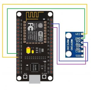 Each I2C device has its own address and the I2C protocol takes care of sending commands to and reading values from the correct device using its address. The Wire library (not to be confused with the OneWire library) is the library that takes care of the I2C protocol. The ESP8266 version of the Wire library is included with the ESP8266 Arduino core. On top of that, a library is needed for each device type that takes care of the device specific I2C commands (sending data, reading values).
For the BMP280 sensor you may use the Adafruit BMP280 library. Using the Adafruit BMP280 library will require you to also install the Adafruit Unified Sensor library and the Adafruit Bus I/O helper library. The easiest way to install these libraries is using the Library Manager that is part of the Arduino IDE (Tools -> Manager Libraries). If you search for BMP280 in the Library Manager and install the Adafruit BMP280 library, you’ll be prompted to install the other libraries as well. There’s an example named bmp280test included in the Adafruit BMP280 library to get you going.
However, there’s a catch: the BMP280 sensor in your kit might listen to I2C address 0x76, as opposed to the library’s default address 0x77. If you connect this sensor correctly and it doesn’t work, replace the following line in the bmp280test example:
status = bmp.begin();
with this line:
status = bmp.begin(BMP280_ADDRESS_ALT, BMP280_CHIPID);
[Actually, that line is already present in the bmp280test example, but commented out.]
This will initiate the sensor using the alternative address BMP280_ADDRESS_ALT which is defined in the library as 0x76.
On the ESP8266, you might need to specify which pins you’re using for I2C. The default pins that the Wire library uses are D2 for SDA and D1 for SCL. If you use these defaults, you won’t need to specify these, nor initiate the Wire library, as this is all taken care of by the BMP280 library.
If, however, you want to use different pins for I2C, use Wire.begin(SDA_PIN, SCL_PIN) with the appropriate pins in your setup function before you start the BMP280 sensor using its begin() function call. It has successfully been tested using Wire.begin(D3, D5), but other pins may be used as well.
Finally, as we are using I2C, you can get rid of the #include <SPI.h> line in the example that includes the SPI library, a totally different protocol for talking to sensors that is unneeded ballast in this case.
If you (really) want, you may also use any alternative BMP280 library, but in that case you’ll be on your own to get it working.
Oh, one more thing. You’ll need to solder headers onto the board before you’ll be able to use it… For convenience, make sure that you solder it in such a way that the sensor itself (a single tiny silver square component on one side of the board, as shown in the pictures) is on the bottom side when you put the board in your breadboard. In that way you’ll be able to read the pin labels while the board is inserted into your breadboard. Excess pins, if any, may be broken off.
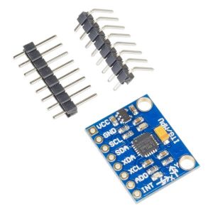 1 * Accelerometer and gyroscope, 3-axis, MPU-6050, including header strips. This sensor has a somewhat different purpose than the other sensors: it is intended to be connected to your Stickuino – yes, the one from the first assignment – as detailed in the requirements of the second assignment, although it is also compatible with the NodeMCU / ESP8266 platform. (So: this is the exception to the rule that you should not mix 3.3V and 5V sensors and platforms. See also below.)
This, again, quite advanced digital sensor contains two sensors in a very tiny package and is mounted on a small board containing some supportive hardware. The sensors are an accelerometer and a gyroscope. It uses the I2C protocol to provide acceleration values (from the accelerometer) and rate of rotation values (from the gyroscope) along each of three spatial axis: x, y and z. As each of the 2 sensors offers values for 3 axis, we say that this sensor offers 6 degrees of freedom (6-DoF).
The following is a description of how to use this board with your Stickuino, as required in the second assignment.
For the MPU-6050 sensor you may use the I2C Device Library by Jeff Rowberg. The I2C Device Library contains drivers for many different I2C sensors, including the MPU-6050, for several embedded platforms, including the Arduino. More details about the project can be found on the project homepage. Details on how to install and use this library are available as well. An example reading the raw values is included.
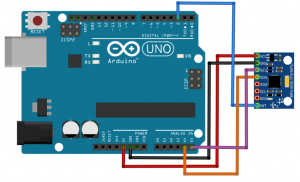 Connecting the MPU-6050 to your Stickuino should be straightforward: SDA should go to A4 and SCL should go to A5 as these are the I2C pins of the Stickuino. Furthermore, it needs a positive (5V, VCC) and negative (GND) power supply connection. Finally, there’s an interrupt pin (INT) that is needed in some applications and this should go to pin 2 of your Stickuino.
Connecting the MPU-6050 to your NodeMCU, if you’d ever want to do so, should be similar. Don’t worry about the 5V versus 3.3V mismatch in this case: the board is powered using 5V (VIN on your NodeMCU) and the supportive components on the board will bridge the difference. You’ll find some help online as well, but again, connecting it to your NodeMCU is not the intention in this assignment.
Again, you’ll need to solder headers onto the board before you’ll be able to use it. Which of the included headers – straight or angled – to use is up to you and might depend on how you’ll mount the board during the assignment. Plan ahead.
Actuators
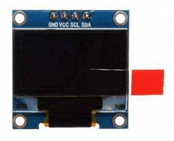 1 * OLED display, 0.96″, 128×64. Just like the 16×2 LCD display in your Interaction technology kit, this display could be considered an actuator. This tiny yet quite advanced display, based on the SDD1306 controller chip, fortunately requires a lot less wiring than the 16×2 LCD display. It uses the I2C protocol to communicate with your NodeMCU, which is the same protocol that your BMP280 and MPU-6050 sensors use and requires only two pins, besides the power supply. The display is graphical in the sense that the individual pixels can be controlled. For convenience, you’ll be using a library that allows you to print text to the display just like you did with the 16×2 LCD display. But you won’t be limited to just simple text. The library includes functions to draw lines, circles, pixels, etc. as well.
As far as the library is concerned, you have two options here:
The Adafruit SSD1306 library. This is library is from the same company as the BMP280 library that you are using. It requires you to also install the Adafruit GFX library that takes care of all the graphical drawing functions. These libraries are again available from the Library Manager in the Arduino IDE. There’s an example included in the Adafruit SSD1306 library to get you going. Make sure that you select the example for the 128×64 I2C display.
However, there are again some catches: the example is configured for a slightly different type of OLED display and requires some tweaks. First of all, the OLED display in your kit listens to I2C address 0x3C instead of the example’s default address 0x3D. This is easily changed in the line that defines SCREEN_ADDRESS. Don’t let the comment on that line suggesting a relation between display address and display size fool you.
 Again, you may get rid of the unneeded #include <SPI.h> in the example. Again, you may want to explicitly specify which pins you’re using for I2C, just like you might have done for the BMP280 sensor. In that case, use Wire.begin(SDA_PIN, SCL_PIN) with the appropriate pins in your setup function before you start the OLED display using its begin() function call. If you don’t do this, the SSD1306 defaults to pin D2 for SDA and pin D1 for SCL. Again, it has successfully been tested using Wire.begin(D3, D5), but other pins may be used as well.
Finally you should that sure that in the example the RESET pin (#define OLED_RESET) is set to -1.
The ThingPulse ESP8266 OLED SSD1306 library. This library is similar to the Adafruit library. There are a number of examples included, such as SSD1306SimpleDemo. This example should work out of the box, depending on the pins you are using for I2C. The example defaults to pin D2 for SDA and pin D1 for SCL. The default I2C address already matches your OLED displays address. If any change is required, look for the line SSD1306 display(0x3c, SDA, SCL) that initializes the display with the address and pins as parameters. Currently it uses the generic SDA and SCL labels that default to D2 and D1, as mentioned, but these are easily changed to explicit pins, e.g. display(0x3c, D3, D5).
Note that although the Wire library is included in the example, there’s no explicit call to the Wire.begin function needed, not even if you are using non-default I2C pins. This call is implicit to the initialization of the display when using this library.
We suggest that you try both libraries and use the one that you like best. They differ with respect to the graphical functions that they offer. The ThingPulse example may be a bit easier to get to work, as it already defaults to the correct I2C address. It also contains a nice feature to build a frame based UI (see SSD1306UiDemo). However, when we start to combine things, specifically more than one I2C device, it could be beneficial to use libraries from a single source for these devices, being the Adafruit libraries.
If you (really) want, you may also use any alternative SSD1306 library, but in that case you’ll be on your own to get it working.
 1 * Micro servo, including arms and screws. A servo motor is just an ordinary motor with an internal position sensor and some electronics. The position feedback from the sensor is used by the on board electronics to keep a certain position or angle, as instructed by the code controlling the servo. This means that you can tell the servo to go to a certain position (between approximately 0 and 180 degrees, or -90 and 90 degrees, depending how you look at it) and it will keep this position until instructed otherwise.
The servo has a 3-pin female connector that can easily be extended in a breadboard friendly way using your male-to-male jumper wires. The brown wire of the servo should be connected to GND. The red wire should be connected to – beware – 5V which is available at the VIN pin of your NodeMCU. This is, in fact, the power supplied by the USB port, circumventing the on board voltage regulator.
As mentioned, you should be very careful in mixing 5V with the NodeMCU / ESP8266 platform. In this case, however, we can get away with it as the servo motor itself operates on 5 Volts and the 5V we supply to it through the red wire doesn’t reach any of the other NodeMCU pins the servo is connected to. The servo may also work if its supply pin is connected to 3.3 Volts, but it will be less powerful in that case, to the point that it is not really usable.
This leaves us with still one wire unconnected: the orange one, which is the control wire of the servo.
As explained during the second lecture on Embedded systems and sensors, a servo is controlled by Pulse Width Modulation (PWM) with the duty cycle indicating the position it should go to and maintain. Fortunately, there’s no need to program all the PWM trickery yourself: the ESP8266 Arduino core comes with an ESP8266 compatible version of the Servo library which you can easily include in your sketch.
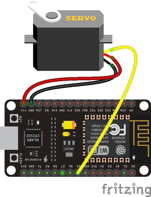 We’ve tested the Sweep example that comes with the Servo library successfully with the orange wire of the servo connected to NodeMCU pin D2, but other pins may be used as well, such as in picture where D5 is being used. If you use the example out of the box, it expects the control wire of servo to be attached to pin 2, which, as discussed in the section on the NodeMCU board, maps to NodeMCU pin D4.
The servo and your NodeMCU board are quite sensitive to power fluctuations. We’ve noticed that the servo can become quite jittery and move in a nervous, random way, because of the power requirements of the servo motor. To solve this issue, the servo comes with a capacitor – by now you should know how this looks – and if you place this between the 5V supply pin and the GND pin of the servo, power should be much more stable and the jitter should disappear. It’s not in the picture, but you should be able to manage this yourself. Please pay attention to the polarity of the capacitor: the shorter leg of the capacitor indicates its negative side. The negative side of the capacitor can also be identified by a light colored band containing minus signs.
The arms and screws that come with the servo can be attached to its axis to create a lever to which, in turn, other objects that need to be moved may be attached.
One thing you’ll notice when using the servo is that it may be quite noisy when it tries to hold its position. This might be annoying in case of extended use in a room where people are present (e.g. your bedroom). To silence your servo, you may turn it off when not in use by calling the servos detach function. Of course you should reattach the servo using the attach function call when you want to control it again. Note that the servo will not hold its position when turned off, but as long as it is not under a lot of load at that time, the internal friction will usually be enough to prevent it to slip.
Supportive components
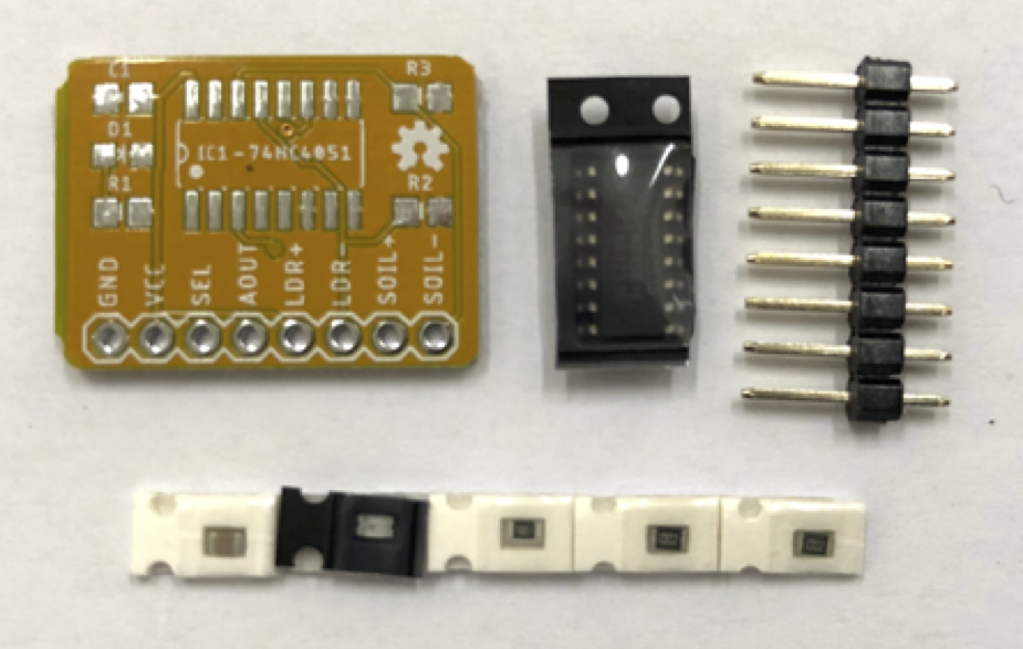 1 * Analog multiplexer SMD soldering exercise. “What’s with this strange yellow board without any components soldered to it yet?”, you may have asked yourself. Well, that’s an Analog multiplexer board, or AMUX board for short.
We included it in the kit for two reasons. Number one is a practical one: your NodeMCU has only a single analog input pin and – as you’ll soon find out – the second assignment requires you to use two analog sensors. We somehow need to extend the number of analog inputs.
The second reason is more conceptual, and it’s the reason why it has not been soldered yet: it offers you the chance to learn how to solder like a pro. You’ve been soldering your Stickuino, which featured so called ‘through hole’ components. The procedure was simple after a bit of practice: stick each component through the holes, turn the board upside down and solder it in place. However, this type of soldering doesn’t scale too well in an industry where things are preferably automated as much as possible. The electronics industry has switched to a different type of soldering that can be efficiently automated: Surface Mount Technology (SMT) using Surface Mount Devices (SMD). SMD soldering involves tiny components that are placed and soldered on top of the printed circuit board, hence the name. You’ll be emulating this usually automated process by hand, using the SMD components that came with the AMUX board, to learn how it’s done, as explained during the towards assignment 2 lecture. And in doing so, you’ll end up with a soldered and working AMUX board that you need for the first reason we mentioned.
This means that if you want to solder your AMUX board, you’ll need to come to the Job Shop during one of the AMUX soldering sessions, as we have the required equipment at your disposal there. As explained during the lectures, this requires reserving a spot in our reservation system. We’ll help you out with this task and explain how things work. Don’t solder the AMUX board using a regular soldering iron. That is not the way to go and you’d miss out on a life-changing experience! (Unless you won’t come to campus and have a soldering iron at your disposal at home; then you could always give it a try…) And don’t solder headers to your AMUX board yet. You should first solder the SMD components to your AMUX board using the equipment we have available in the Job Shop.
Here are the soldering instructions for your AMUX board:
- The small bag in your IoT kit labelled ‘Analog multiplexer SMD soldering exercise’ contains a printed circuit board, an analog multiplexer IC (the chip; the biggest component featuring 16 pins), a strip with 5 tiny components, being a capacitor, a led, a 1k Ohm resistor and 2 times a 10k Ohm resistor, and finally an 8-pin header strip. The size of the 5 tiny components is ‘0805’ which is actually the largest size available for these type of SMD components.
- You should first apply solder paste to the pads of your AMUX board, as explained during the towards assignment 2 lecture. This will be demonstrated in the Job Shop. Less solder paste is usually better than too much solder paste.
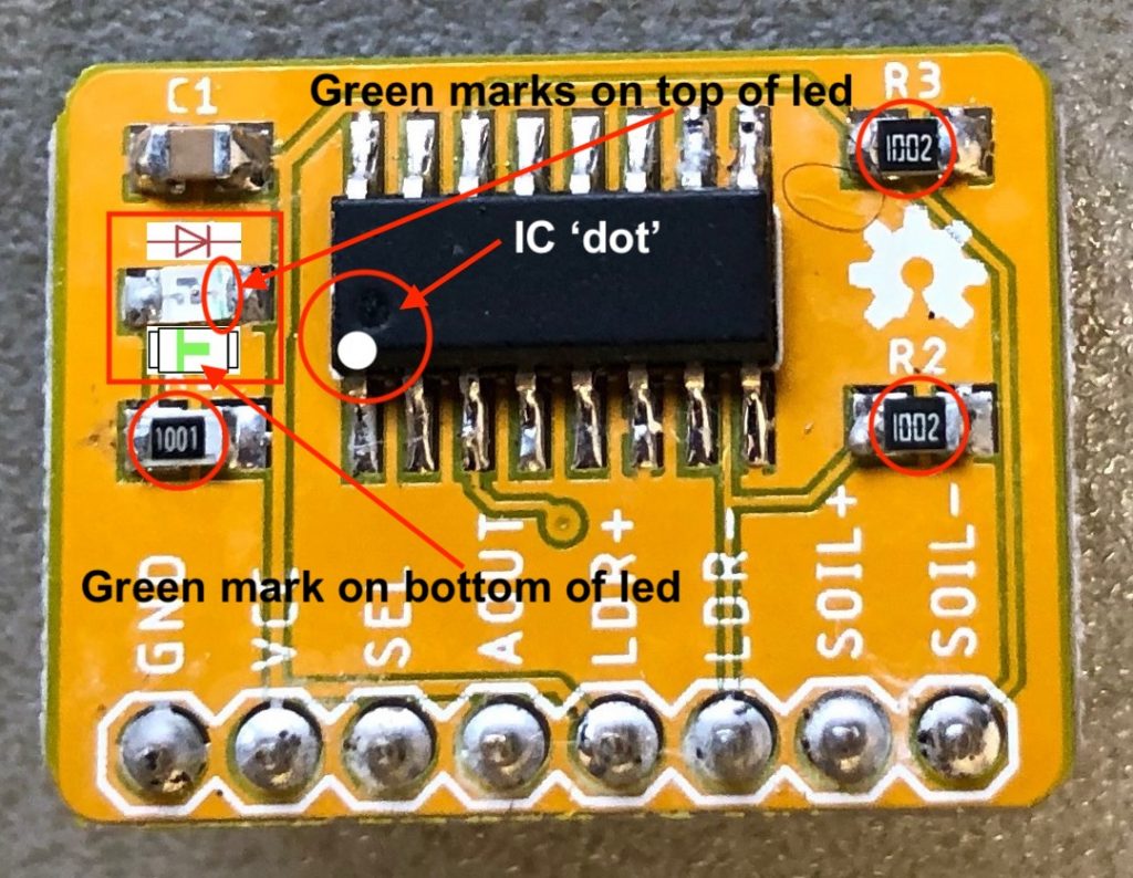 You should then place the components on the pads on top of the solder paste in the right place and with the correct orientation using tweezers. Again, tools and help are available in the Job Shop.
- Be careful not to loose (too many) components. They are tiny and have a tendency to ‘shoot away’ from your tweezers if you don’t have a secure grip, never to be found again. We have a limited amount of spares available.
- The annotated picture of the AMUX board on the side supports the description below. Enlarge it by clicking on it and keep it open for reference while reading the instructions.
- The capacitor is the brownish/beige component. It should go in place of C1 on the board. Orientation does not matter.
- The 1k Ohm resistor is the black component labelled ‘1001’, which stands for 100 x 101. It should go in place of R1 on the board. Orientation does not matter, as long as the label is visible on top.
- The 10k Ohm resistors are the black components labelled ‘1002’, which stands for 100 x 102. These should go in place of R2 and R3 on the board. Again, orientation does not matter, as long as the labels are visible on top.
- The remaining tiny component, packaged in the black part of the strip, is the led. It should go in place of D1 on the board (remember, a led being a Light Emitting Diode, hence the ‘D’ designation).
 This time, orientation does matter. It may be difficult to spot, but on the board you’ll see a small >| sign between the pads where the led should go. This is an abstraction of the symbol for a led used in schematics. The vertical bar (|) indicates the negative side, in this case the right hand pad of D1 (the pad closest to the IC).
 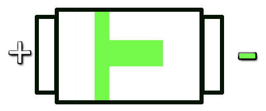 Now we still need to find out what the negative side of the led is. Fortunately, there’s a small green T-shaped mark on the bottom of the led. The horizontal ‘standing leg’ of the T indicates the negative side of the led. It should point towards the IC. If you look very closely (see the annotated photo of the board on the right), you’ll find some green marks on the top side of the led as well. These should then be on the right, closest to the IC.
 - The analog multiplexer IC is the final component to the place on your AMUX board. It should go in place of IC1. As you may have guessed, orientation is again important. On the board is a white dot in the bottom left hand corner of the space reserved for IC1. This indicates pin 1 of the IC and should match with the circular depression (‘dot’) on the IC itself when placing it (‘dot-on-dot’).
- Make sure that each component touches the solder paste (and the pads beneath it) with all its pins. You may push on them a bit using the tweezers to make them stick a bit better to the solder paste. Make sure that the IC is aligned well enough that each of the pins touches the correct corresponding pad. Make sure that the IC pins are not ‘off by one’ (touching an adjacent pad instead of the intended one). [Obligatory Star Wars reference.]
- Please check again. Fixing errors is difficult with these tiny components and especially the IC is hard to remove and replace, given its 16 pins.
- That being said, a lot of other things are not really critical. The components don’t have to be aligned perfectly, as long as they touch the correct pads, as they will mostly self-align during soldering. Furthermore, any solder paste smeared off the pads and onto the board will find its way back to the pads, thanks to the solder mask on the board.
- After placing the components and making sure they are mounted correctly, you should solder your AMUX board using a reflow oven. This will be demonstrated in the Job Shop. See the slides of the towards assignment 2 lecture for some movies of what happens during the process.
- After soldering the board, you should visually inspect it for defects, most prominently solder bridges between the pins of the IC and tombstoning (components that are standing upright like a tombstone, you’ll recognize it when you see it). Again, see the slides of the towards assignment 2 lecture for some pictures and movies of these defects.
- If you’re happy with the result, you may finally solder the header strip to your AMUX board. Use a regular soldering iron for this. It’s easiest to stick the header in your breadboard, put the AMUX board on top and solder the pins. The components should be on the top side. You might want to do the same for the BMP280 board in one go. (Please note: the single tiny silver square component on one side of the board should be on bottom when you put the BMP280 board in your breadboard.) And also for the MPU-6050 board. (Please note: which of the included headers – straight or angled – to use is up to you and might depend on how you’ll mount the board during the assignment.)
- All done! You may proceed to test and use your AMUX board. A first test would be to power it up (GND to GND and VCC to 3.3V of your NodeMCU board) and see if the power led lights up. If you encounter any problems, please ask for help during one of the practical sessions.
Let’s go back to the first reason we included the AMUX board: extend the number of analog inputs. How does it work? The AMUX board features an 74HC4051 analog multiplexer IC. It is able to multiplex 8 analog inputs. That means that it has 8 analog input pins and can relay the input value it reads on any of those pins to a single analog output pin. Which of the analog input pins is read and relayed to the analog output pin is controlled by 3 more digital input lines, being the address lines. It should not come as a surprise that 2^3 = 8. By connecting 3 I/O lines of a microcontroller to the address lines of the 74HC4051 and outputting a bit pattern consisting of 3 HIGH/LOW values the microcontroller indicates which of the analog inputs (numbered from 0 to 7) it is interested in. This analog input is read by the 74HC4051 and the value is relayed to its analog output pin, which in turn is connected to an analog input pin of the microcontroller. So, writing LOW/LOW/LOW to the 3 address lines will yield the value of analog input 0, whereas writing HIGH/LOW/HIGH to the 3 address lines will yield the value of analog input 5. And so on, and so on.
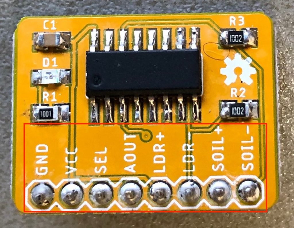 In our case, we just need 2 analog inputs. That’s why we’ve crippled the 74HC4051 a bit on the AMUX board: there’s only a single address line brought out to the header pins (the SEL pin, meaning SELect). Writing LOW to this pin will yield the value of analog input 0 and writing HIGH to this pin will yield the value of analog input 1. These values are available on header pin AOUT (meaning Analog OUTput). By now, you’ll probably understand that you’ll need to connect the analog input of your NodeMCU (pin A0) to AOUT of the AMUX board and control the select pin of the AMUX board by connecting it to one of the I/O pins on your NodeMCU. Furthermore, there’s a GND and VCC pin on the header of the AMUX board that should be connected to the GND and 3.3V pins of your NodeMCU respectively.
But what is connected to analog input 0 and analog input 1 of the 74HC4051 on your AMUX board? If you have a look at the header pins of your AMUX board, you’ll see two pins labeled LDR+ and LDR-, suggesting that a Light Dependent Resistor (LDR) could be connected to these pins. You are right! That’s exactly what they are intended for! And the analog value that the LDR outputs is available on analog input 0 of the 74HC4051, and thus on AOUT whenever SEL is LOW.
But won’t we need a voltage divider then to translate a variable resistance – as output by the LDR – to a variable (analog) voltage, as expected by an analog pin? Great thinking again! Indeed, there should be a voltage divider involving a 10k Ohm resistor in the LDR circuit, as you’ve used before. And it should be located on the input side of the 74HC4051 IC, as that IC also expects an analog voltage (and not a variable resistance) on its inputs pins.
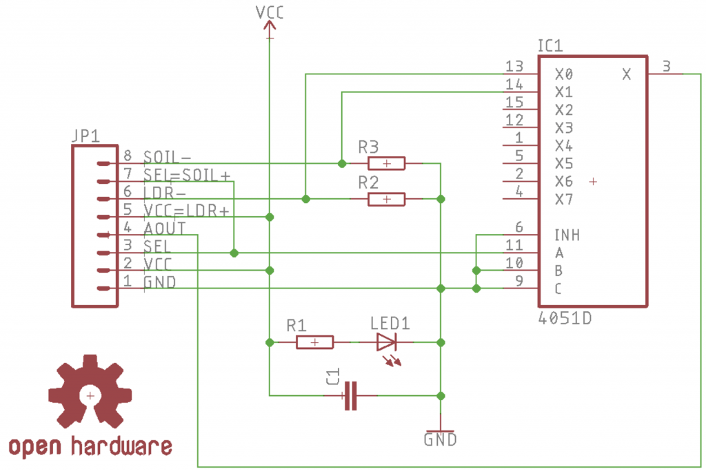 However, if you take a close look at the schematics of the AMUX board, you’ll see that the voltage divider – using a 10k Ohm resistor – is already in place on the AMUX board itself! Isn’t that convenient? That means that you can just connect the LDR to the LDR+ and LDR- pins of the AMUX board, without any additional components. Note that for the LDR polarity does not matter.
The same trick applies to the soil moisture sensor. As you’ll notice, the two remaining pins of the AMUX board are labeled SOIL+ and SOIL-. It’ll be no surprise that the soil moisture sensor should be directly connected to these pins. Again, the soil moisture sensor would normally require a voltage divider, as explained in the section on this sensor. Again, this voltage divider is already present on the AMUX board and its output is available on analog input 1 of the 74HC4051, and thus on AOUT whenever SEL is HIGH. Again, that means that you can just connect the soil moisture senor to the SOIL+ and SOIL- pins of the AMUX board, without any additional components. Note that for the soil moisture sensor polarity does not matter.
Now it is also clear why we won’t be using the comparator board. We are interested in analog values for which the soil moisture sensor in combination with the AMUX board and its included voltage divider will do just fine, giving us the benefit of being able to multiplex the analog pin in order to connect the LDR as well. You may use the included female-to-female jumper wires to conveniently connect the soil moisture sensor to your breadboard. Hint: use male-to-male jumper wires to extend the female-to-female jumper wires and create the female-to-male jumper wires that you actually need. Lots of gender issues, here.
There’s one more trick up the sleeve of the AMUX board. It has to do with solving the corrosion problem due to electrolysis in case of extended use of the soil moisture sensor. Can you spot it by looking at the schematics? And again you are right! The SOIL+ line is not connected to VCC but to SEL. That means that the soil moisture sensor is not powered continuously, as it would be in the case of a connection to VCC, but only if the SEL pin is HIGH. And that is exactly the time at which you select analog input 1 of the AMUX board, i.e. the soil moisture sensor input. In other words, selecting the soil moisture sensor for reading a value also powers the soil moisture sensor, whereas it is connected to GND otherwise (i.e. when selecting the LDR). Corrosion can thus be prevented as much as possible by defaulting to selecting the LDR (by writing LOW to SEL), and only switching to the soil moisture sensor (by writing HIGH to SEL) temporarily when a reading is needed. Again, give the soil moisture sensor some time (~100ms) after switching it on (or off) to stabilize before you do a reading.
If you look at the schematics of the AMUX board, you’ll see a few more components that have not yet been accounted for. These are a power led and its mandatory current limiting resistor (1k Ohm is this case), as well as a capacitor that’s included to stabilize the power supply of the 74HC4051 IC.
Turning the difficulty up to eleven
If you’re done playing around with all the individual components, a nice exercise is combining the BMP280 sensor and the OLED display in one circuit. Both of these devices use the I2C protocol. As mentioned before, I2C uses a bus architecture with multiple devices sharing the same data and clock lines. That means that in such a combined circuit both devices should be connected to the same two I2C pins (SDA, SCL) on your NodeMCU. Or actually, they should be daisy chained. It also means that you have to include and use all of the libraries for these devices in the same sketch.
If you opted for the Adafruit SSD1306 library, combining it with the Adafruit BMP280 library is quite straightforward. Just copy the relevant parts of the bmp280test example into the Adafruit OLED example to create a single integrated sketch. If you opted to use the default I2C pins, you end up with a sketch without an explicit call to the Wire.begin function. If you don’t use the default I2C pins, make sure that you call the Wire.begin function only once, as you have only a single I2C bus.
If you opted for the ThingPulse ESP8266 OLED SSD1306 library, you should keep in mind that initializing the OLED display implicitly calls the Wire.begin function, initializing the I2C bus and defining the I2C pins. This has two consequences. First, in your code you should initialize the OLED display using e.g. display.init() before initializing the BMP280 sensor using e.g. bmp.begin(). Second, any explicit Wire.begin call that you may have added to get the Adafruit BMP280 example working with non-default I2C pins should be removed again if you copy code from the Adafruit BMP280 example into the ThingPulse OLED example to create a single integrated sketch. Otherwise, the I2C bus would be initialized twice. You thus end up with a sketch without an explicit call to the Wire.begin function, regardless of whether you used default or non-default I2C pins.
More in store
If you made it through to here, most of your worries are already over, hardware-wise. There might be more worries ahead, but these will be more related to software. It’s now time to move on to the second assignment!