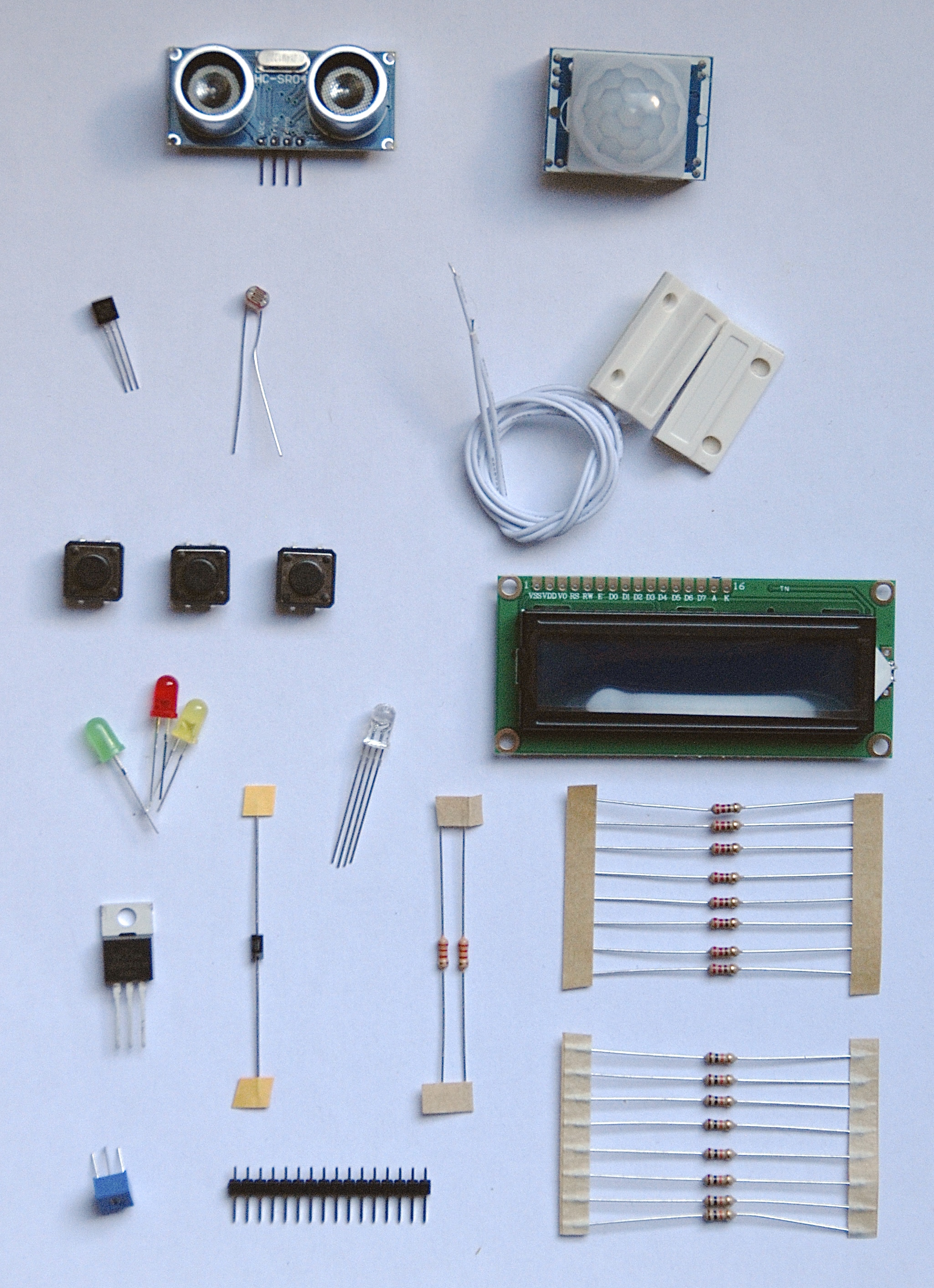
On this page, we take a more detailed look at the contents of the Interaction technology sensor kit, to gain a basic understanding of the sensors and actuators that are included, as well as their supportive components. For a primer on how to connect these sensors and actuators to your Stickuino, have a look at the hooking things up page.
Sensors
 1 * Ultrasonic distance sensor, HC-SR04. This ultrasonic sensor uses sonar to determine distance to an object in the same way that bats or dolphins do. How cool is that! It comes complete with and ultrasonic transmitter and receiver module on a single board. The sensor sends out inaudible acoustic pulses and measures the time that passes until it receives an echo. It offers non-contact range detection from a few centimeters to a few meters. This is one of the more advanced digital sensors in your kit.
1 * Motion sensor, PIR, HC-SR501. This motion detector, also known as a Passive InfraRed (PIR) sensor, is not unlike the motion detectors used in domestic alarm systems. It uses an infrared (= heat) sensor with a number of segments and a lens to decide whether it ‘sees’ motion, which makes it a binary sensor.
1 * Light sensor, LDR, GL5516. This sensor is a Light Dependent Resistor (LDR). The lower the light level the higher the resistance. To be able to read this analog sensor, you’ll need to build a voltage divider.
1 * Temperature sensor, DS18B20 compatible. This quite advanced digital sensor uses the 1-wire protocol, which coincidentally – what’s in a name – uses three wires. Connecting it will require a so called pull-up resistor.
1 * Magnetic contact sensor, including magnet. This one looks a lot like the door and window sensors you might know from domestic alarm systems. Internally, the magnetic field generated by the permanent magnet closes a tiny switch, also known as a reed contact, whenever the magnet is close enough. For all practically purposes it can be considered to be a switch, just like a push button, and can be wired the same way. It’s sometimes called a Normally Closed (NC) contact, as the doors and windows that these contacts are used for are supposed to be closed in their normal state. This is opposed to the Normally Open (NO) designation that better fits a push button.
3 * Push button. Although humble in appearance, these are binary sensors that interface your microcontroller with the outside world. Switches in general need a pull-up resistor to be read by a microcontroller.
Actuators
1 * LCD display, 2×16 with backlight. This display offers a way to interface your microcontroller to the outside world. It’s one of the main output devices in your kit. In fact, it could be considered an actuator. This display is compatible with the ubiquitous HD44780 LCD controller. To be able to use it on the breadboard, you’ll need to solder the included 16 pins header strip to the display. It also needs a series resistor for the backlight, as well as a variable resistor to control its contrast.
1 * LED, 5mm, red. A modern day light bulb. Use it in series with a resistor or it will burn fiercly for a very short amount of time, and only once.
1 * LED, 5mm, green. Also available in green…
1 * LED, 5mm, yellow. …and yellow. However simple these leds may look, these are actually binary actuators. Note that you may dim a led by using Pulse Width Modulation (PWM). In that case it becomes an analog actuator.
1 * RGB LED, 5mm, common cathode. This led is basically three leds (red, green and blue) in one package. Each of the colors has its own leg. And the fourth (longest) leg is a common leg – shared between all colors. The common leg is the cathode: the negative side of the led. To light up the RGB led you need to connect the positive sides to your microcontroller I/O pins (one for each color) and the common leg to the negative power supply pin (GND). Writing a HIGH (1) value to the corresponding pin will light up a color. Writing a LOW (0) value will turn it off.
As you might have guessed, common anode RGB leds do exist as well. In that case the leds share a common positive side: the anode. This is somewhat counter-intuitive, as it means that you need to connect the negative sides (one for each color) to your microcontroller I/O pins and write a LOW (0) value to the corresponding pin to light up a color. Writing a HIGH (1) value will turn it off. As we usually prefer a HIGH (1) value to turn things on, we’ve included a common cathode RGB led in the workshop kit.
You’ll need three series resistors to connect this component; only one will not do. Note that finding the longest leg might be a bit difficult as on certain leds it’s barely longer than the other pins, but you’ll manage. By dimming the individual colors through PWM, you’ll be able to create any color you like.
1 * Mosfet, IRLZ34N. (It may also read IRFZ34N in your kit.) A mosfet could be considered to be an electronic switch, much like a transistor, but with certain benefits. It will be used to fire the main actuator of your assignment: the missing piece, a.k.a. the toilet freshener. The motor of the toilet freshener uses too much power to be directly connected to your microcontroller. Furthermore, the voltage level differs (1,5V for the toilet freshener, 5V for the microcontroller). The mosfet bridges these differences: the microcontroller controls the mosfet (switch) which in turn switches the toilet freshener. The mosfet needs to be hooked up in a specific way. Doing it differently will / may cause damage. It must be used in combination with a pull-down resistor as well as a flyback diode.
Supportive components
1 * Diode, 1N4007. A diode operates like an electronic value, allowing current to pass through it in only one way. This diode is needed as a so called flyback diode in combination with the mosfet, to prevent damaging it.
8 * Resistor, 220 Ohm. Resistors are, well, resistors. These resistors will be mainly used in series with the leds and the LCD display backlight to prevent them from blowing up. Spares included.
8 * Resistor, 10k Ohm. These resistors are mainly used as pull-up resistors for the push buttons and the magnetic contact sensor. They are also needed for building a voltage divider in combination with the light sensor and for connecting the mosfet. Spares included.
2 * Resistor, 2.2k Ohm. One of these resistors will be used as a pull-up resistor for the temperature sensor. The other one is a spare.
1 * Variable resistor, 10k Ohm. This variable resistor, also known as a potentiometer or just pot, runs from 0 Ohm to 10k Ohm, depending on the position of the dial. It’s needed to adjust the contrast of the LCD display.
1 * Header strip for LCD, male, straight, 16 pins. This header strip must be soldered to the LCD display to be able to use it on your breadboard.